Mitsubishi Outlander GS45X. Manual - part 46
HEADLIGHT
TSB Revision
CHASSIS ELECTRICAL
54A-181
.
COMMENTS ON TROUBLE SYMPTOM
If the daytime running lights do not illuminate, the
wiring harness connector(s), the bulb or the
ETACS-ECU may have a problem.
.
PROBABLE CAUSES
• Burned-out daytime running light bulb
• Malfunction of the daytime running light relay
• Malfunction of the ETACS-ECU
• Damaged harness wires and connectors
DIAGNOSIS
Required Special Tools:
• MB991223: Harness Set
• MB992006: Extra Fine Probe
• MB991958: Scan Tool (M.U.T.-III Sub Assembly)
• MB991824: V.C.I.
• MB991827: M.U.T.-III USB Cable
• MB991910: M.U.T.-III Main Harness A
STEP 1. Check that the tail/stop lights and headlights
operate.
Check that the tail/stop lights and headlights illuminate nor-
mally.
Q: Do the tail/stop lights and headlights operate normally?
YES : Go to Step 2.
NO : Check the tail/stop lights and the headlights (Refer to
trouble symptom chart
STEP 2. Check the daytime running light bulb.
(1) Remove the daytime running light bulb.
(2) Verify that the daytime running light bulb is not damaged or
burned out.
Q: Is the daytime running light bulb in good condition?
YES : Go to Step 3.
NO : Replace the fog light bulb. Verify that the daytime
running lights illuminate normally.
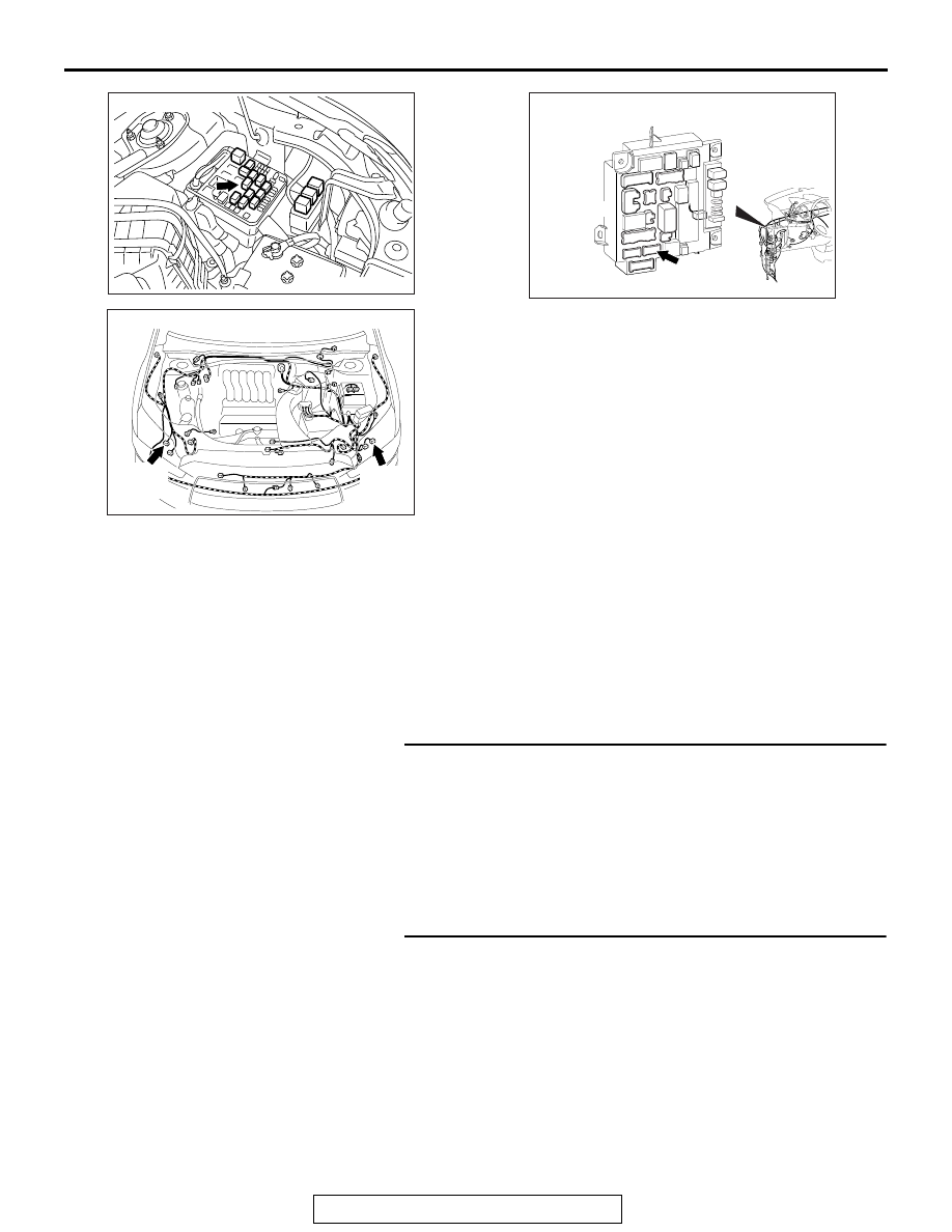
AC702950AF
Connector: A-23X
AC901112
Connectors: A-63, A-64
A-63 (B)
AS
A-64 (B)
ACA02655AW
Connector: C-312