Mitsubishi Outlander (2013+). Manual - part 717
 

  Index      Mitsubishi     Mitsubishi Outlander - service repair manual 2013 year


Search            


Content   ..  715  716  717  718   ..


Mitsubishi Outlander (2013+). Manual - part 717


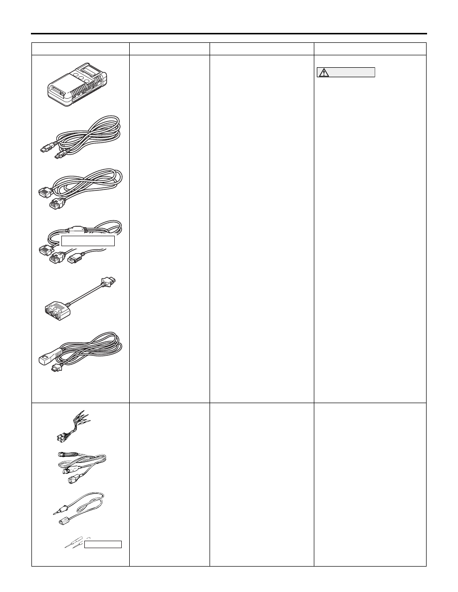
MB991910

MB991826

MB991955

MB991911

MB991824

MB991827

MB991825

a

b

c

d

e

f

DO NOT USE

SPECIAL TOOL

CONTROLLER AREA NETWORK (CAN)

54C-4

MB991955

a. MB991824
b. MB991827
c. MB991910
d. MB991911
e. MB991825
f. MB991826

M.U.T.-III sub-assembly

a. Vehicle communication 

interface (V.C.I.)

b. M.U.T.-III USB cable
c. M.U.T.-III main harness 

A (for vehicles with CAN 
communication)

d. M.U.T.-III main harness 

B (for vehicles without 
CAN communication)

e. Measuring adapter 

harness

f. M.U.T.-III trigger 

harness

CAN bus diagnostics

CAUTION

For vehicles with CAN 
communication, use the 
M.U.T.-III main harness A to 
send simulated vehicle 
speed. If you connect the 
M.U.T.-III main harness B 
instead, the CAN 
communication does not 
function correctly.

MB991223

a

d

c

b

DO NOT USE

BA

MB991223

a. MB991219
b. MB991220
c. MB991221
d. MB991222

Wiring harness set

a. Check harness
b. LED harness
c. LED harness adapter
d. Probe

Continuity check and voltage 
measurement at wiring 
harness or connector

a. For checking connector 

pin contact pressure

b. For checking power supply 

circuit

c. For checking power supply 

circuit

d. For connecting a locally 

sourced tester

Tool

Number

Name

Use

MB992006

TEST EQUIPMENT

CONTROLLER AREA NETWORK (CAN)

54C-5

TEST EQUIPMENT

M1548304300281

Test equipment

Name

Use

AC000019

Digital multimeter

Checking CAN bus circuit (for resistance and voltage 
measurements)

SERVICE PRECAUTIONS

M1548302100270

MB992006

Extra fine probe

Continuity check and voltage 
measurement at wiring 
harness or connector

MB991709

Wiring harness set

Checking the ABS-ECU

Tool

Number

Name

Use

Warnings in diagnosis section

Details regarding warning

CAUTION

When servicing a CAN bus line, earth yourself by 
touching a metal object such as an unpainted 
water pipe. If you fail to do, a component 
connected to the CAN bus line may be broken.

CAUTION

A digital multimeter should be used.

When measuring resistance value or voltage in 
CAN bus lines, use a digital multimeter. If not 
using a digital multimeter, the equipments, which 
are connected through the CAN communication 
lines, may be damaged.

CAUTION

When measuring the resistance, disconnect the 
negative battery terminal.

Disconnect the negative battery terminal when 
measuring the resistance value in the CAN bus 
line. If you fail to do so, the equipments, which 
are connected through the CAN communication 
lines, may be damaged.

CAUTION

The test wiring harness should be used.

Always use the test harness when measuring the 
voltage or resistance value at the female 
connector. If you fail to do so, connectors may be 
damaged.

PRECAUTIONS ON HOW TO REPAIR THE CAN BUS LINES

CONTROLLER AREA NETWORK (CAN)

54C-6

PRECAUTIONS ON HOW TO REPAIR THE CAN BUS LINES

M1548301900273

PRECAUTIONS ON HOW TO REPAIR THE 
CAN BUS LINES

AC204696

Added wire

No good

4AB

If the CAN bus line(s) are repaired, renew all the 

twisted wires between the end connectors. If the 
wiring harness is partially repaired, or only 
CAN_L or CAN_H line is repaired, noise suppres-
sion is deteriorated, causing a communication 
error.

AC203824

Within 10 cm

Connector

Twisted wire

AH

If the connector or wire on the main bus line or the 

sub-bus wire is replaced, the frayed end of the 
twisted wire should be within 10 cm from the con-
nector. If it exceeds 10 cm, twist the wiring har-
ness just like the original twisted wire. If the 
frayed end exceeds 10 cm, noise suppression is 
deteriorated, causing a communication error.

CAUTION

The strand end of the twist wire should be within 
10 cm from the connector.

AC203824

10 cm

Connector

Twisted wire

AB

If you repair the wire due to a defective 
connector or its terminal or harness wire, you 
should cut the wire so that the strand end of the 
twist wire should be within 10 cm from the 
connector as shown. If it exceeds 10 cm, twist 
the wiring harness just like the original twisted 
wire. If the strand end exceeds 10 cm, a 
communication error may be caused.

CAUTION

Strictly observe the specified wiring harness 
repair procedure.

When you repair a CAN bus line, observe the 
precautions on how to repair the CAN bus line 
strictly. Refer to 

P.54C-6

. If a new wire is added 

or a splice point is modified for the CAN_L or 
CAN_H line, an error in the CAN communication 
may be caused.

Warnings in diagnosis section

Details regarding warning

EXPLANATION ABOUT THE M.U.T.-III CAN BUS DIAGNOSTICS

CONTROLLER AREA NETWORK (CAN)

54C-7

AC202856

ECU

ECU

ECU

ECU

Good

No good

Terminator resistor

Open
circuit
point

Open
circuit
point

Terminator resistor

AF

: Shows main bus line. 
: Shows sub bus line. 
: Shows restored CAN bus line. 

If a sub-bus line is repaired, splice a new wire directly 

into the main bus line. If a new wire is spliced into 
the sub-bus line, which is connected to another 
device, the CAN communication will be disabled.

PRECAUTIONS ON HOW TO REPAIR THE 
TERMINATOR RESISTOR

If one-side terminator resistor is broken, the CAN 
communication will continue although noise suppres-
sion is deteriorated. No diagnosis codes may be set 
even if the terminator resistor was broken. If a dam-
age is found, replace the ECU which incorporates 
the defective terminator resistor.

CAN BUS LINE REPAIR HARNESS (PART 
NAME AND NUMBER)

Part name

Part number

Twist pair cable

MN151514

EXPLANATION ABOUT THE M.U.T.-III CAN BUS 

DIAGNOSTICS

M1548300100694

The M.U.T.-III CAN bus diagnostics carries out the 
three checks below automatically, and then displays 
current condition of the CAN bus lines according to 
the check results.


Content   ..  715  716  717  718   ..