Mitsubishi Outlander (2013+). Manual - part 711
ETACS
CHASSIS ELECTRICAL
54A-329
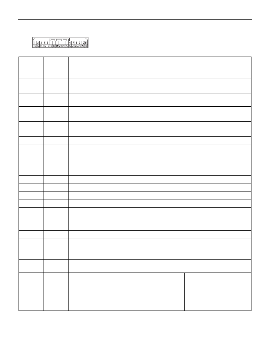
CONNECTOR: C-416
ACC00008AB
Terminal
No.
Terminal
code
Check item
Check condition
Normal
condition
1
−
−
−
−
2
SHF
Input from the front height sensor
Ignition switch: ON
0.5 to 4.5 V
3
SGF
Front height sensor earth
Always
1 V or less
4
AMB-
Earth (ambient temperature
sensor)
Always
1 V or less
5
MGL
Headlamp levelling unit (LH) earth
Always
1 V or less
6
MGR
Headlamp levelling unit (RH) earth
Always
1 V or less
7
SBF
Rear height sensor power supply
Ignition switch: ON
4.2 to 5.7 V
8
HWA
Headlamp washer output
When headlamp washer is ON
1 V or less
9
AMB+
Ambient temperature sensor input
Always
0.2
− 2.72 V
10
−
−
−
−
11
HLO
Headlamp (LO) output
When headlamp (LO) is ON
1 V or less
12
−
−
−
−
13
F/HI
Cooling fan (HI) output
When cooling fan HI is operating
1 V or less
14
−
−
−
−
15
−
−
−
−
16
N.HO
Output to horn
When horn sounds
1 V or less
17
−
−
−
−
18
HHI
Headlamp (HI) output
When headlamp (HI) is ON
1 V or less
19
−
−
−
−
20
BFSW
Brake fluid switch input
Brake fluid switch: ON
1 V or less
21
− 22
−
−
−
−
23
F/LO
Cooling fan (LO) output
When cooling fan LO is operating 1 V or less
24
MBL
Headlamp levelling unit (LH) power
supply
Ignition switch: ON
System
voltage
25
MBR
Headlamp levelling unit (RH) power
supply
Ignition switch: ON
System
voltage
26
MSL
Output to the headlamp levelling
unit (LH)
Ignition switch:
ON
When the
levelling motor
is stopped
1 V or less
When the
levelling motor
is operating
16% to 84%
of system
voltage