Mitsubishi Outlander (2013+). Manual - part 650
MB991910
MB991826
MB991955
MB991911
MB991824
MB991827
MB991825
a
b
c
d
e
f
DO NOT USE
HEADLAMP
CHASSIS ELECTRICAL
54A-85
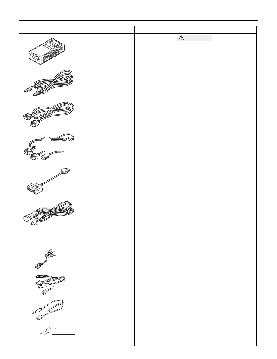
MB991955
a. MB991824
b. MB991827
c. MB991910
d. MB991911
e. MB991825
f. MB991826
M.U.T.-III
sub-assembly
a. Vehicle
Communicati
on Interface
(V.C.I.)
b. M.U.T.-III
USB cable
c. M.U.T.-III
main harness
A (Vehicles
with CAN
communicatio
n system)
d. M.U.T.-III
main harness
B (Vehicles
without CAN
communicatio
n system)
e. M.U.T.-III
measure
adapter
f. M.U.T.-III
trigger
harness
CAUTION
For vehicles with CAN
communication, use M.U.T.-III
main harness A to send
simulated vehicle speed. If you
connect M.U.T.-III main harness B
instead, the CAN communication
does not function correctly.
Diagnosis code, service data and
actuator test check.
MB991223
a
d
c
b
DO NOT USE
BA
MB991223
a. MB991219
b. MB991220
c. MB991221
d. MB991222
Harness set
a. Check
harness
b. LED harness
c. LED harness
adapter
d. Probe
Continuity check and voltage
measurement at harness wire or
connector
a. For checking connector pin
contact pressure
b. For checking power supply
circuit
c. For checking power supply
circuit
d. For connecting a locally sourced
tester
Tool
Number
Name
Use