Mitsubishi Outlander (2013+). Manual - part 638
MB991910
MB991826
MB991955
MB991911
MB991824
MB991827
MB991825
a
b
c
d
e
f
DO NOT USE
COMBINATION METER
CHASSIS ELECTRICAL
54A-37
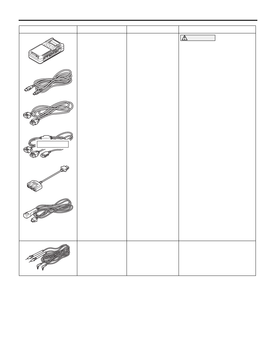
MB991955
a. MB991824
b. MB991827
c. MB991910
d. MB991911
e. MB991825
f. MB991826
M.U.T.-III
sub-assembly
a. Vehicle
Communication
Interface (V.C.I.)
b. M.U.T.-III USB
cable
c. M.U.T.-III main
harness A
(Vehicles with CAN
communication
system)
d. M.U.T.-III main
harness B
(Vehicles without
CAN
communication
system)
e. M.U.T.-III measure
adapter
f. M.U.T.-III trigger
harness
CAUTION
For vehicles with CAN
communication, use M.U.T.-III
main harness A to send
simulated vehicle speed. If you
connect M.U.T.-III main harness
B instead, the CAN
communication does not
function correctly.
Combination meter (incorporating
the meter-ECU) check (Diagnosis
code, service data, actuator test)
MB991499
MB991499
Measurement probe
Measurements of voltage and
resistance value
NOTE: M.U.T.-II attached probe
(Commercial probes can also be
used.)
Tool
Number
Name
Use