Mitsubishi Outlander (2013+). Manual - part 637


  Index      Mitsubishi     Mitsubishi Outlander - service repair manual 2013 year


Search            


Content   ..  635  636  637  638   ..


Mitsubishi Outlander (2013+). Manual - part 637


IMMOBILIZER SYSTEM <Vehicles without keyless operation system>

CHASSIS ELECTRICAL

54A-33

NOTE: 

*

: When insert ignition key to ignition switch or turn ignition switch from ACC to ON.

ON-VEHICLE SERVICE

HOW TO REGISTER KEY ID

M1541104300521

For the details of key registration procedure, refer to the ID registration procedure manual.
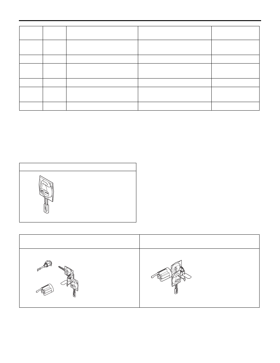
KEY SUPPLY UNIT

Ignition key (with transmitter)

AC502118

KEY SUPPLY UNIT LIST FOR OTHER THAN INDIVIDUAL KEY

Full service key set <vehicles with keyless entry 
system>

Steering lock service key set <vehicles with 
keyless entry system>

ACA00906

AC808657

14

ANTP

Immobilizer antenna output (+) When immobilizer 

authentication

*

70 Vp-p

15

16

SIGI

Immobilizer signal input/output When immobilizer 

authentication

*

0 to 5 V (pulse 
signal)

17

18

WCLK

Immobilizer CLOCK input

When immobilizer 

authentication

*

0 to 5 V (pulse 
signal)

19 to 24

Terminal 
number

Terminal 
code

Check item

Check condition

Normal condition

Door service key set 

NOTE: It is the key that comes with the door 
service key set and the tailgate service key set. It 
can only be used for locking and unlocking, and 
it cannot start the engine.

AC608188

IMMOBILIZER SYSTEM <Vehicles without keyless operation system>

CHASSIS ELECTRICAL

54A-34

RECEIVER ANTENNA

REMOVAL AND INSTALLATION

M1541107500018

CAUTION

When receiver antenna has been replaced, turn the ignition switch to ON and OFF once.

ACB05639

1

AB

Removal steps 

• Upper glove box assembly (Refer 

to GROUP 52A 

− Instrument panel 

assembly .)

1. Receiver antenna

COMBINATION METER

CHASSIS ELECTRICAL

54A-35

COMBINATION METER

SERVICE SPECIFICATIONS

M1540200200805

Item

Standard value

Speedometer indication range km/h

at 20 km/h

20.25 

− 22.25

at 40 km/h

40.5 

− 44.5

at 80 km/h

81.5 

− 86.5

at 120 km/h

122.5 

− 128.5

at 160 km/h

162.5 

− 169.5

at 200 km/h

202.5 

− 210.5

at 240 km/h

242.5 

− 251.5

Tachometer indicating tolerance r/min

Engine speed at 600 r/min

± 100

Engine speed at 3,000 r/min

± 100

Engine speed at 5,000 r/min

± 100

Engine speed at 6,000 r/min

± 100

2WD Nominal resistance of the fuel gauge unit 

Stopper position "F"

13.0 

± 1.0

Stopper position "E"

120.0 

± 1.0

Fuel gauge unit float height mm

Stopper position "F"

201.6

Stopper position "E"

18.0

4WD Nominal resistance of the fuel gauge unit 

Ω Main

Stopper position "F"

6.5 

± 1.0

Stopper position "E"

44.7 

± 1.0

Sub

Stopper position "F"

6.5 

± 1.0

Stopper position "E"

75.3 

± 1.0

Fuel gauge unit float height mm

Main

Stopper position "F"

166.2

Stopper position "E"

38.8

Sub

Stopper position "F"

48.8 

± 3.0

Stopper position "E"

238.0 

± 3.0

COMBINATION METER

CHASSIS ELECTRICAL

54A-36

SPECIAL TOOLS

M1540200300437

Tool

Number

Name

Use

ACB05421

MB992745

MB992746

MB992744

MB992747

MB992748

a

b

c

d

e

DO NOT USE

AB

a. MB992744
b. MB992745
c. MB992746
d. MB992747
e. MB992748

a. Vehicle 

communication 
interface-Lite 
(V.C.I.-Lite)

b. V.C.I.-Lite main 

harness A (for 
vehicles with CAN 
communication)

c. V.C.I.-Lite main 

harness B (for 
vehicles without 
CAN 
communication)

d. V.C.I.-Lite USB 

cable short

e. V.C.I.-Lite USB 

cable long

Combination meter (incorporating 
the meter-ECU) check (Diagnosis 
code, service data, actuator test)


Content   ..  635  636  637  638   ..