Mitsubishi Outlander (2013+). Manual - part 634
IMMOBILIZER SYSTEM <Vehicles without keyless operation system>
CHASSIS ELECTRICAL
54A-21
IMMOBILIZER SYSTEM <Vehicles without keyless
operation system>
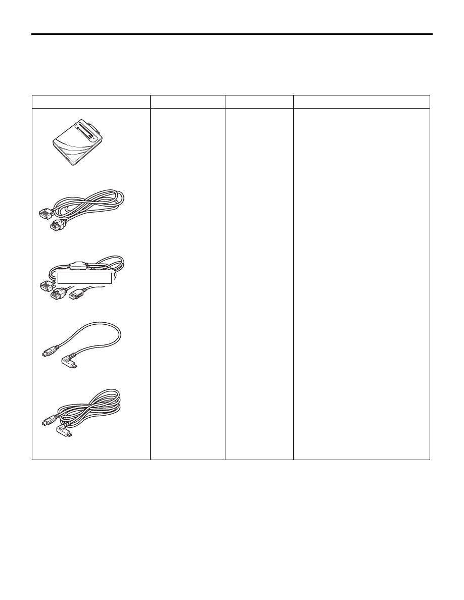
SPECIAL TOOLS
M1541106600120
Tool
Number
Name
Use
ACB05421
MB992745
MB992746
MB992744
MB992747
MB992748
a
b
c
d
e
DO NOT USE
AB
a. MB992744
b. MB992745
c. MB992746
d. MB992747
e. MB992748
a. Vehicle
communicatio
n
interface-Lite
(V.C.I.-Lite)
b. V.C.I.-Lite
main harness
A (for vehicles
with CAN
communicatio
n)
c. V.C.I.-Lite
main harness
B (for vehicles
without CAN
communicatio
n)
d. V.C.I.-Lite
USB cable
short
e. V.C.I.-Lite
USB cable
long
Diagnosis code check