Mitsubishi Outlander (2013+). Manual - part 464


  Index      Mitsubishi     Mitsubishi Outlander - service repair manual 2013 year


Search            


Content   ..  462  463  464  465   ..


Mitsubishi Outlander (2013+). Manual - part 464


TROUBLESHOOTING

ACTIVE STABILITY CONTROL SYSTEM (ASC)

35C-31

STEP 8. Check for wheel bearing looseness

NOTE: Loose wheel bearing may increase the gap 
between the wheel speed sensor and the wheel 
speed detection magnet encoder. Check the wheel 
bearing for looseness. <Refer to GROUP 26 

 Wheel 

Bearing Axial Play Check . (front), GROUP 27A 


Wheel Bearing Axial Play Check  (rear-2WD) or 
GROUP 27B 

 Wheel Bearing Axial Play Check  

(rear-4WD)>

Q: Is the check result normal?

YES : 

Go to Step 9.

NO : 

Replace the wheel bearing <front> or rear 
wheel hub assembly <rear>. <Refer to 
GROUP 26 

− Front Axle Hub Assembly  

(front), GROUP 27A 

− Rear Axle Hub 

Assembly  (rear-2WD) or GROUP 27B 

− 

Rear Axle Hub Assembly  (rear-4WD)> 
Then go to Step 12.

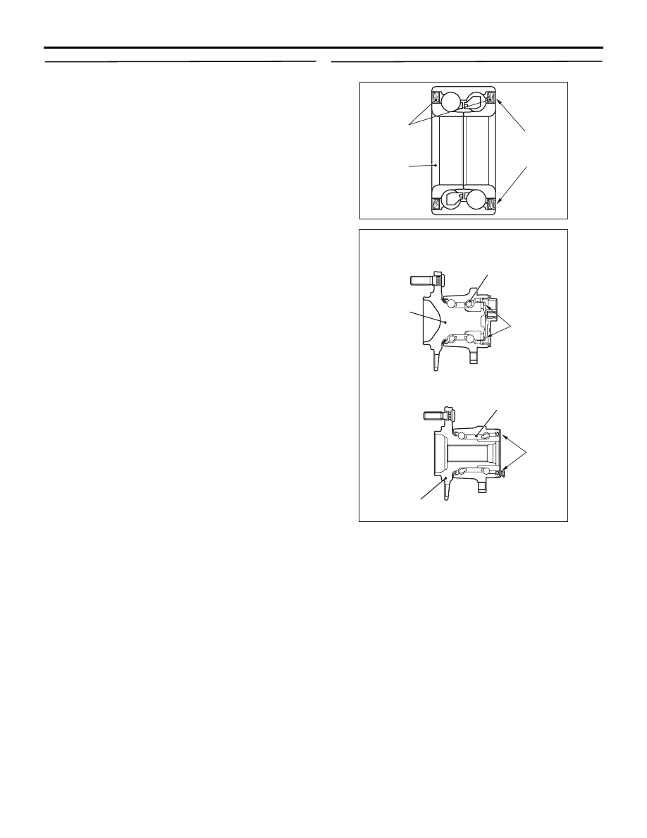
STEP 9. Check of wheel speed detection encoder

AC504925

Oil seal

Magnetic
encoder

AD

Wheel
bearing

<Front>

AC808708

Ball bearing

Rear hub 
assembly

Magnetic 
encoder

<2WD>

<Rear>

<4WD>

Rear wheel bearing

Rear hub 
assembly

Magnetic 
encoder

AC

Check the encoder for adhesion of foreign materials 
or deformation.

Q: Is the check result normal?

YES : 

Go to Step 10.

NO (Adhesion of foreign materials) : 

Remove the 

foreign materials and clean the encoder so 
as not to disturb the magnetization pattern 
on it while taking care of the magnet, 
magnetic substance, and magnetic 
attraction. Then go to Step 12.

NO (Deformation) : 

Replace the wheel bearing 

<front> or rear wheel hub assembly <rear>. 
<Refer to GROUP 26 

− Front Axle Hub 

Assembly  (front), GROUP 27A 

− Rear Axle 

Hub Assembly  (rear-2WD) or GROUP 27B 
− Rear Axle Hub Assembly  (rear-4WD)> 
Then go to Step 12.

TROUBLESHOOTING

ACTIVE STABILITY CONTROL SYSTEM (ASC)

35C-32

STEP 10. Check whether the diagnosis code is 
reset.
(1) Erase the diagnosis code.
(2) Drive the vehicle at 20 km/h or higher.

NOTE: The ABS warning lamp does not turn OFF 
in some cases unless the vehicle runs at 20 km/h 
or higher.

Q: Is the diagnosis code No.C1046, C1047, C1048 or 

C1049 set?
YES : 

Replace the wheel speed sensor (Refer to 

P.35C-97

 <front> or 

P.35C-97

 <rear>). 

Then go to Step 11.

NO : 

Intermittent malfunction (Refer to GROUP 
00 

− How to Use Troubleshooting/How to 

Cope with Intermittent Malfunctions ).

STEP 11. Check whether the diagnosis code is 
reset.
(1) Erase the diagnosis code.
(2) Drive the vehicle at 20 km/h or higher.

NOTE: The ABS warning lamp does not turn OFF 
in some cases unless the vehicle runs at 20 km/h 
or higher.

Q: Is the diagnosis code No.C1046, C1047, C1048 or 

C1049 set?
YES : 

Replace the hydraulic unit (integrated with 

ASC-ECU) (Refer to 

P.35C-95

). Then go to 

Step 12.

NO : 

This diagnosis is complete.

STEP 12. Check whether the diagnosis code is 
reset.
(1) Erase the diagnosis code.
(2) Drive the vehicle at 20 km/h or higher.

NOTE: The ABS warning lamp does not turn OFF 
in some cases unless the vehicle runs at 20 km/h 
or higher.

Q: Is the diagnosis code No.C1046, C1047, C1048 or 

C1049 set?
YES : 

Return to Step 1.

NO : 

This diagnosis is complete.

Code No. C104B FL inlet valve


Code No. C104F FR inlet valve


Code No. C1053 RL inlet valve


Code No. C1057 RR inlet valve


Code No. C105F FL outlet valve


Code No. C1063 FR outlet valve


Code No. C1067 RL outlet valve


Code No. C105B RR outlet valve


Code No. C1200 FL-RR cut valve


Code No. C1204 FR-RL cut valve


Code No. C1208 FL-RR suction valve


Code No. C120C FR-RL suction valve

CAUTION

• If there is any problem in the CAN bus lines, 

an incorrect diagnosis code may be set. Prior 
to this diagnosis, diagnose the CAN bus lines 
(Refer to GROUP 54C 

 CAN Bus Diagnostics 

Table ).

• Whenever ECU is replaced, ensure that the 

CAN bus lines are normal.

• When the hydraulic unit (integrated with 

ASC-ECU) is replaced, always carry out the 
calibration of the steering wheel sensor, the G 
and yaw rate sensor and brake fluid pressure 
sensor (Refer to 

P.35C-93

P.35C-94

 and 

P.35C-94

).

OPERATION

• ASC-ECU contains the power supply circuit (+BV 

terminal) for the solenoid valve. The solenoid 
valve is energised by the valve relay, which is 
incorporated in ASC-ECU.

• The valve relay, which is incorporated in 

ASC-ECU, is always energising the solenoid 
valve unless the initial check is in progress when 
the ignition switch is turned on, and the recurrent 
system check is in progress.

• ASC-ECU activates the solenoid valve by turning 

on its driving transistor.

DIAGNOSIS CODE SET CONDITIONS

These diagnosis codes will be set under the cases 
below:

TROUBLESHOOTING

ACTIVE STABILITY CONTROL SYSTEM (ASC)

35C-33

• The solenoid valve is not energized even after 

ASC-ECU has turned on the driving transistor 
(Open circuit is present in the power supply cir-
cuit to the ASC-ECU solenoid valve, or the valve 
relay has failed).

• After ASC-ECU has turned off the driving transis-

tor, the solenoid valve still remains energized 
(short in the solenoid valve circuit).

• When a solenoid valve failure is detected

PROBABLE CAUSES

• ASC-ECU malfunction

DIAGNOSIS PROCEDURE

STEP 1. M.U.T.-III CAN bus diagnosis
Use M.U.T.-III to diagnose the CAN bus lines.

Q: Is the check result normal?

YES : 

Go to Step 3.

NO : 

Repair the CAN bus lines (Refer to GROUP 
54C 

− CAN Bus Diagnostics Table ). On 

completion, go to Step 2.

STEP 2. Diagnosis code recheck after resetting 
CAN bus lines

Q: Is the relevant diagnosis code set?

YES : 

Go to Step 3.

NO : 

This diagnosis is complete.

STEP 3. Check whether the diagnosis code is 
reset.
Erase the diagnosis code.

Q: Is the relevant diagnosis code set?

YES : 

Replace the hydraulic unit (integrated with 

ASC-ECU) (Refer to 

P.35C-95

). Then go to 

Step 4.

NO : 

Intermittent malfunction (Refer to GROUP 
00 

− How to Use Troubleshooting/How to 

Cope with Intermittent Malfunctions ).

STEP 4. Check whether the diagnosis code is 
reset.
Erase the diagnosis code.

Q: Is the relevant diagnosis code set?

YES : 

Return to Step 1.

NO : 

This diagnosis is complete.

Code No. C2104 Valve power supply circuit

CAUTION

• If there is any problem in the CAN bus lines, 

an incorrect diagnosis code may be set. Prior 
to this diagnosis, diagnose the CAN bus lines 
(Refer to GROUP 54C 

 CAN Bus Diagnostics 

Table ).

• Whenever ECU is replaced, ensure that the 

CAN bus lines are normal.

• When the hydraulic unit (integrated with 

ASC-ECU) is replaced, always carry out the 
calibration of the steering wheel sensor, the G 
and yaw rate sensor and brake fluid pressure 
sensor (Refer to 

P.35C-93

P.35C-94

 and 

P.35C-94

).

OPERATION

• ASC-ECU contains the power supply circuit (+BV 

terminal) for the solenoid valve. The solenoid 
valve is energised by the valve relay, which is 
incorporated in ASC-ECU.

• The valve relay, which is incorporated in 

ASC-ECU, is always energising the solenoid 
valve unless the initial check is in progress when 
the ignition switch is turned on, and the recurrent 
system check is in progress.

DIAGNOSIS CODE SET CONDITIONS

This diagnostic trouble codes will be set when the 
solenoid valve supply voltage is not within the stand-
ard value.

PROBABLE CAUSES

Current trouble

• Fusible link malfunction

• Damaged wiring harness and connectors

• Abnormality in battery or alternator

• ASC-ECU malfunction

TROUBLESHOOTING

ACTIVE STABILITY CONTROL SYSTEM (ASC)

35C-34

Past trouble

• Carry out diagnosis with particular emphasis on 

wiring harness and connector failures between 
the power supply circuit (+BV terminal) to 
ASC-ECU solenoid valve or earth circuit (GND1, 
GND2 terminal). For diagnosis procedures, refer 
to How to treat past trouble (GROUP 00 

− How to 

Use Troubleshooting/How to Treat Past Trouble ).

DIAGNOSTIC PROCEDURE

STEP 1. M.U.T.-III CAN bus diagnosis
Use M.U.T.-III to diagnose the CAN bus lines.

Q: Is the check result normal?

YES : 

Go to Step 3.

NO : 

Repair the CAN bus lines (Refer to GROUP 
54C 

− CAN Bus Diagnostics Table ). On 

completion, go to Step 2.

STEP 2. Diagnosis code recheck after resetting 
CAN bus lines

Q: Is the diagnosis code No. C2104 set?

YES : 

Go to Step 3.

NO : 

This diagnosis is complete.

STEP 3. Battery check
Refer to GROUP 54A 

− Battery Test .

Q: Is the battery in good condition?

YES : 

Go to Step 4.

NO : 

Replace the battery. Then go to Step 10.

STEP 4. Charging system check
Refer to GROUP 16 

− On−vehicle Service/Alternator 

Output Line Voltage Drop Test .

Q: Is the charging system in good condition?

YES : 

Go to Step 5.

NO : 

Repair or replace the charging system 
component(s). Then go to Step 10.

STEP 5. Fusible link check: Check the fusible link 
No.4 and SBF7.
Visually check for open circuit in the fusible link No.4 
and SBF7.

Q: Is the check result normal?

YES : 

Go to Step 7.

NO : 

Go to Step 6.

STEP 6. Resistance measurement at ASC-ECU 
connector
(1) Disconnect the connector, and measure at the 

wiring harness side.

(2) Disconnect the fusible link No.SBF7.
(3) Resistance between the +BV terminal and the 

body earth.

OK: No continuity

Q: Is the check result normal?

YES : 

Replace the fusible link No.4 or SBF7. Then 

go to Step 10.

NO : 

The short circuit may be present in the 
power supply circuit. Repair the wiring 
harness between the ASC-ECU connector 
+BV terminal and the fusible link, and then 
replace the fusible link No.4 or SBF7. Then 
go to Step 10.

STEP 7. Voltage measurement at the ASC-ECU 
connector
(1) Disconnect the connector, and measure at the 

wiring harness side.

(2) Measure the voltage between the +BV terminal 

and the body earth.

OK: Approximately system voltage

Q: Is the check result normal?

YES : 

Go to Step 8.

NO : 

The open circuit may be present in the 
power supply circuit. Repair the wiring 
harness between the ASC-ECU connector 
+BV terminal and the fusible link. Then go to 
Step 10.

STEP 8. Resistance measurement at ASC-ECU 
connector
(1) Disconnect the connector, and measure at the 

wiring harness side.

(2) Resistance between the GND1 terminal and the 

body earth, and between the GND2 terminal and 
the body earth

OK: Continuity exists (2 

 or less)

Q: Is the check result normal?

YES : 

Go to Step 9.

NO : 

An open circuit may be present in the earth 
circuit. Repair the wiring harness between 
the ASC-ECU connector GND1 terminal 
and the body earth, and between the 
ASC-ECU connector GND2 terminal and 
the body earth. Then go to Step 10.

STEP 9. Check whether the diagnosis code is 
reset.
Erase the diagnosis code.

Q: Is the diagnosis code No.C2104 set?


Content   ..  462  463  464  465   ..