Mitsubishi Outlander (2013+). Manual - part 440
SERVICE SPECIFICATIONS
ANTI-SKID BRAKING SYSTEM (ABS)
35B-3
SERVICE SPECIFICATIONS
M1352000300964
Item
Standard value
Wheel speed sensor current mA
5.9
− 8.4 or 11.8 − 16.8
Wheel speed sensor insulation resistance M
Ω
5 or more
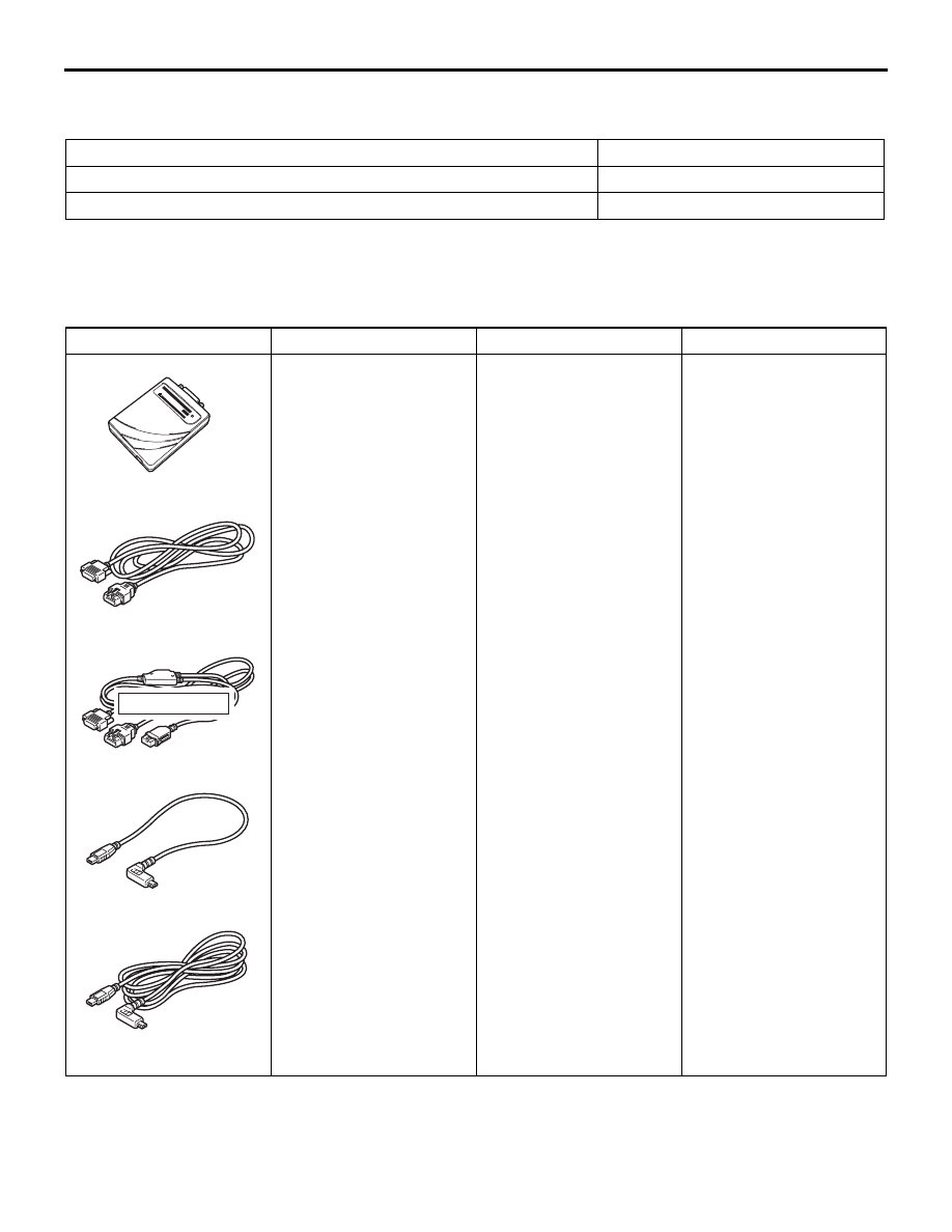
SPECIAL TOOLS
M1352000601883
Tool
Number
Name
Use
ACB05421
MB992745
MB992746
MB992744
MB992747
MB992748
a
b
c
d
e
DO NOT USE
AB
a. MB992744
b. MB992745
c. MB992746
d. MB992747
e. MB992748
a. Vehicle
communication
interface-Lite
(V.C.I.-Lite)
b. V.C.I.-Lite main
harness A (for vehicles
with CAN
communication)
c. V.C.I.-Lite main
harness B (for vehicles
without CAN
communication)
d. V.C.I.-Lite USB cable
short
e. V.C.I.-Lite USB cable
long
ABS check (Diagnosis
code display and data list
display by M.U.T.-III)