Mitsubishi Outlander (2013+). Manual - part 351
MB991910
MB991826
MB991955
MB991911
MB991824
MB991827
MB991825
a
b
c
d
e
f
DO NOT USE
CRUISE CONTROL
ENGINE AND EMISSION CONTROL
17-5
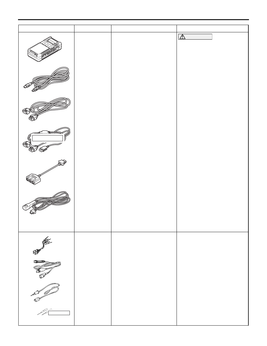
MB991955
a: MB991824
b: MB991827
c: MB991910
d: MB991911
e: MB991825
f: MB991826
M.U.T.-III sub assembly
a: Vehicle communication
interface (V. C. I.)
b: M.U.T.-III USB cable
c: M.U.T.-III main harness A
(Vehicles with CAN
communication system)
d: M.U.T.-III main harness B
(Vehicles without CAN
communication system)
e: M.U.T.-III measurement
adapter
f: M.U.T.-III trigger harness
CAUTION
M.U.T.-III main harness A
should be used. M.U.T.-III
main harness B should not be
used for this vehicle. If you
connect M.U.T.-III main
harness B instead, the CAN
communication does not
function correctly.
Checking data list
MB991223
a
d
c
b
DO NOT USE
BF
MB991223
a: MB991219
b: MB991220
c: MB991221
d: MB991222
Harness set
a: Check harness
b: LED harness
c: LED harness adaptor
d: Probe
Making voltage and resistance
measurement during
troubleshooting
a: Connector pin contact
pressure inspection
b: Power circuit inspection
c: Power circuit inspection
d: Commercial tester
connection
Tool
Number
Name
Use