Mitsubishi Outlander (2013+). Manual - part 346
STARTING SYSTEM
ENGINE ELECTRICAL
16-20
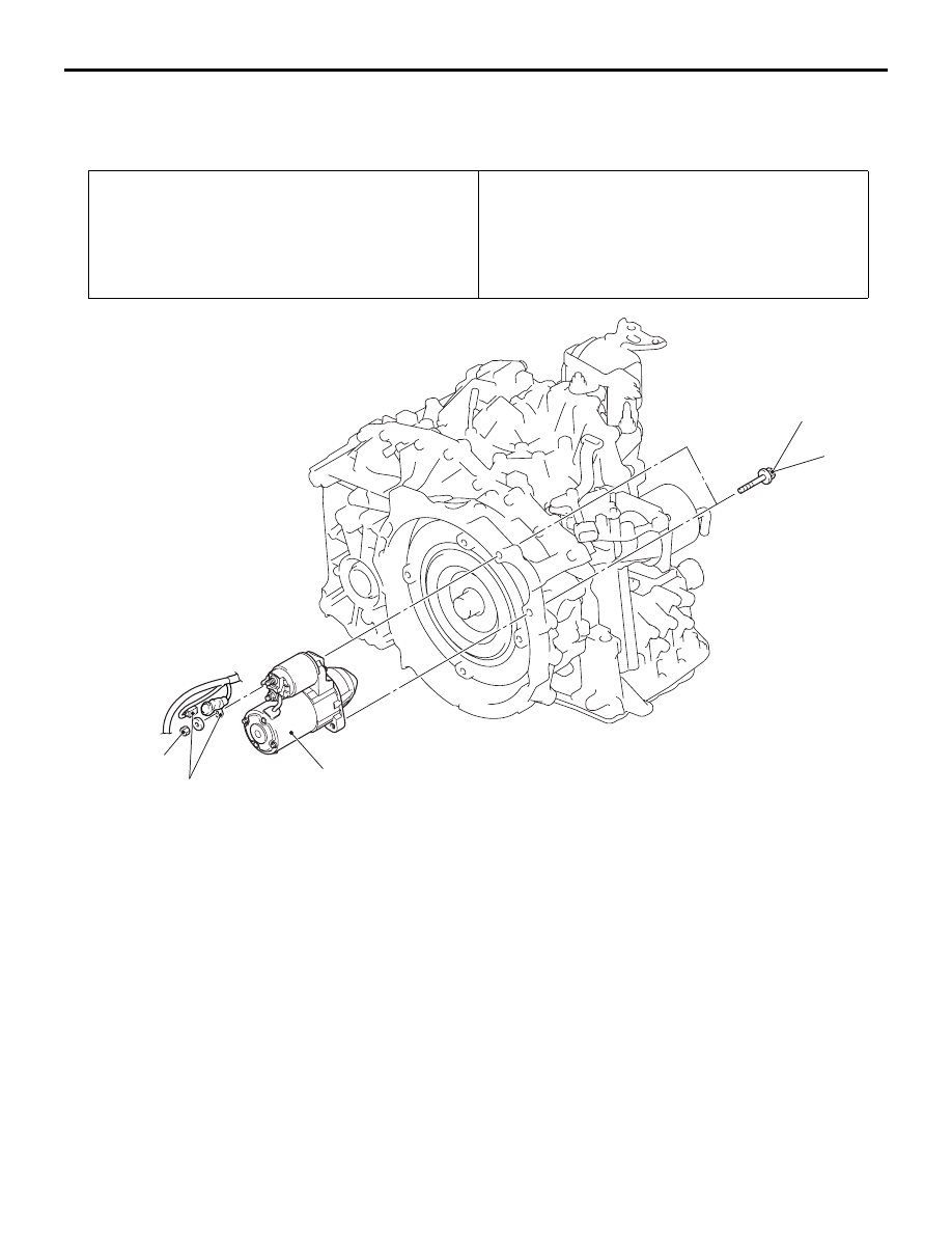
STARTER MOTOR ASSEMBLY
REMOVAL AND INSTALLATION
M1162001003348
Pre-removal operation
• Air cleaner intake duct and air intake hose removal (Refer
to GROUP 15
− Air cleaner ).
• Battery and battery tray removal (Refer to GROUP 54A −
Battery ).
• Engine room under cover panel removal (Refer to
GROUP 51
− Under cover ).
Post-installation operation
• Engine room under cover panel installation (Refer to
GROUP 51
− Under cover ).
• Battery and battery tray installation (Refer to GROUP 54A
− Battery ).
• Air cleaner intake duct and air intake hose installation
(Refer to GROUP 15
− Air cleaner ).
AC611210
36 ± 9 N·m
11 ± 1 N·m
2
AC
3
1
Removal steps
<<
A
>>
•
Throttle body assembly mounting
bolt (Refer to GROUP 13A
−
Throttle Body Assembly .)
1.
Starter mounting bolt
<<
B
>>
2.
Starter connector and terminal
<<
B
>>
3.
Starter assembly
REMOVAL SERVICE POINTS
<<A>> THROTTLE BODY ASSEMBLY
MOUNTING BOLT REMOVAL
1. Remove the throttle body assembly together with
the water hose from the inlet manifold.
2. Tie the removed throttle body assembly with a
string at a position where it will not interfere with
the operation.
<<B>> STARTER CONNECTOR AND
TERMINAL/STARTER ASSEMBLY
REMOVAL
1. Slide the starter assembly, and remove the starter
connector and terminal.
2. Remove the starter assembly from the lower front
of the engine.