Mitsubishi Outlander (2013+). Manual - part 311
 

  Index      Mitsubishi     Mitsubishi Outlander - service repair manual 2013 year


Search            


Content   ..  309  310  311  312   ..


Mitsubishi Outlander (2013+). Manual - part 311


TROUBLESHOOTING

MULTIPOINT FUEL INJECTION (MPI)

13A-125

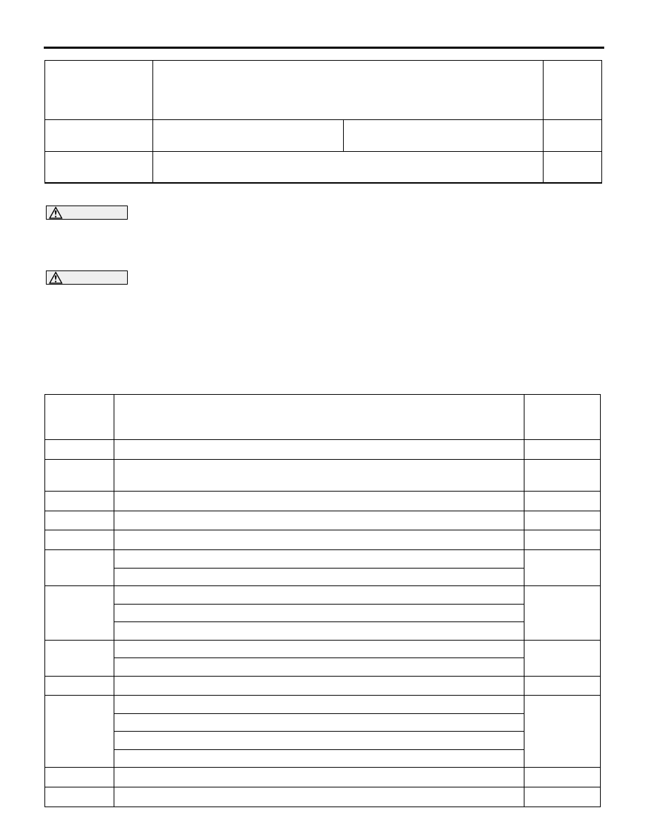
PROBLEM SYMPTOMS TABLE

WARNING

When touching the throttle valve, surely shut off the driving circuits of the throttle valve. In 
the event that the throttle valve is operated, a finger might be injured as the result of being 
caught by the throttle valve.

CAUTION

During troubleshooting if the ignition switch is turned to ON with the connectors, etc. disconnected, 
some diagnosis code may be saved in other system. After the troubleshooting is completed, always 
make sure the diagnosis codes of the entire systems. If it is found that some diagnosis codes have 
been outputted, erase them.

NOTE: When the racing (2,000 to 5,000 r/min or more) continues on the vehicle stopped with no load during 
the specified time or more, the increase in the engine speed might be limited. This comes from the engine 
protection and control functions and is not a malfunction.

Cooling 
performance

Overheating

The temperature of engine cooling 
water is extremely high.

18

ECO mode 
indicator

In running, the ECO mode indicator shows nothing.

24

Item

Trouble Symptom

Inspectio

Procedur
e No.

Inspection 
Procedure 
No.

Inspection Item

Reference 
Page

1

The communication between M.U.T.-III and engine-ECU is not possible

P.13A-126

2

The engine warning lamp does not illuminate right after the ignition switch is 
turned the ON position

P.13A-127

3

The engine warning lamp remains illuminating and never goes out

P.13A-128

4

Starting impossible (starter not operative)

P.13A-128

5

Starting impossible (starter operative but no initial combustion)

P.13A-132

6

Starting impossible (initial combustion but no complete combustion)

P.13A-133

Improper starting (long time to start)

7

Unstable idling (rough idling, hunting)

P.13A-135

Improper idling speed (too high or too low)

Engine stalls during idling (die out)

8

The engine stalls when starting the car (pass out)

P.13A-137

The engine stalls when decelerating

9

Engine does not revolve up

P.13A-137

10

Hesitation, sag

P.13A-138

Poor acceleration

Stumble

Surge

11

The feeling of impact or vibration when accelerating

P.13A-140

12

The feeling of impact or vibration when decelerating

P.13A-141

TROUBLESHOOTING

MULTIPOINT FUEL INJECTION (MPI)

13A-126

SYMPTOM PROCEDURES

Inspection Procedure 1: The Communication Between M.U.T.-III and Engine-ECU is Not Possible

OPERATION

• Battery voltage is applied to the diagnosis con-

nector terminal.

• The diagnosis connector terminal is earthed to 

the vehicle body.

COMMENTS ON TROUBLE SYMPTOM

• When the communication between M.U.T.-III and 

the engine-ECU is impossible, the CAN bus line, 
power supply circuit of the diagnosis connector, 
and/or earthing circuit could possibly be defec-
tive. The communication cannot be achieved 
either if the wrong vehicle type is selected on 
M.U.T.-III.

PROBABLE CAUSES

• Defective diagnosis connector.

• Open/short circuit or harness damage in diagno-

sis connector circuit or loose connector contact.

• Defective CAN communication.

• Defective M.U.T.-III.

• Failed engine-ECU

DIAGNOSIS PROCEDURE

STEP 1. Check the Vehicle Communication 
Interface (V.C.I.) operations

• Connect the M.U.T.-III to the diagnosis connector.

• When the power of Vehicle Communication Inter-

face (V.C.I.) is turned to ON, the indicator lamp of 
the Vehicle Communication Interface (V.C.I.) illu-
minates in green.

OK: The indicator lamp of the Vehicle Com-
munication Interface (V.C.I.) illuminates in 
green.

Q: Is the check result normal?

YES : 

Go to Step 10.

NO : 

Go to Step 2.

STEP 2. Check battery.

• Check battery (Refer to GROUP 54A − Battery − 

On-vehicle Service 

− Battery Test ).

Q: Is the check result normal?

YES : 

Go to Step 3.

NO : 

Replace the battery.

13

Knocking

P.13A-141

14

Ignition timing deviation

P.13A-142

15

Run on (dieseling)

P.13A-143

16

Odour, white smoke, black smoke, and high-concentration CO/HC during idling

P.13A-143

17

Battery run down

P.13A-145

18

Overheating

P.13A-146

19

Engine-ECU power supply, engine control relay, ignition switch

−IG1 system

P.13A-147

20

Fuel pump system

P.13A-149

21

A/C compressor relay system

P.13A-151

22

Ignition circuit system

P.13A-152

23

Engine oil pressure switch system

P.13A-154

24

In running, the ECO mode indicator shows nothing

P.13A-155

Inspection 
Procedure 
No.

Inspection Item

Reference 
Page

TROUBLESHOOTING

MULTIPOINT FUEL INJECTION (MPI)

13A-127

STEP 3. Perform voltage measurement at 
diagnosis connector.

• Voltage between terminal power supply line and 

body earth.

OK: System voltage

Q: Is the check result normal?

YES : 

Go to Step 6.

NO : 

Go to Step 4.

STEP 4. Check harness between ETACS-ECU 
connector terminal MUT and diagnosis 
connector terminal.

• Check power supply line for open/short circuit.

Q: Is the check result normal?

YES : 

Go to Step 5.

NO : 

Repair or replace the connector, or repair 
the damaged harness wire.

STEP 5. Check harness between battery and 
ETACS-ECU terminal +B1 connector.

• Check power supply line for open/short circuit.

Q: Is the check result normal?

YES : 

Check fuse in the ETACS-ECU, and replace 

if necessary. If the fuse is normal, replace 
the ETACS-ECU.

NO : 

Repair or replace the connector, or repair 
the damaged harness wire.

STEP 6. Perform resistance measurement at 
diagnosis connector.

• Resistance between terminals earth lines and 

body earth.

OK: Continuity (2 

 or less)

Q: Is the check result normal?

YES : 

Go to Step 7.

NO : 

Check intermediate connector, and repair if 

necessary. If intermediate connector is 
normal, check and repair the harness 
between the diagnosis connector terminals 
earth lines and body earth.

• Check earthing line for open circuit 

and damage.

STEP 7. Continuity check on ETACS-ECU 
connectors

• Disconnect connectors, and measure at 

ETACS-ECU side.

• Continuity check between terminal +B1 and IG1.

OK: Continuity 

Q: Is the check result normal?

YES : 

Go to Step 8.

NO : 

Repair or replace the connector, or check 
fuse in the ETACS-ECU, and replace if 
necessary. If the fuse is normal, replace the 
ETACS-ECU.

STEP 8. Check harness between battery and 
ETACS-ECU connector terminal +B1.

• Check power supply line for damage.

Q: Is the check result normal?

YES : 

Go to Step 9.

NO : 

Repair the damaged harness wire.

STEP 9. Check harness between ETACS-ECU 
connector MUT and diagnosis connector 
terminal.

• Check power supply line for damage.

Q: Is the check result normal?

YES : 

Refer to the M.U.T.-III reference manual.

NO : 

Repair the damaged harness wire.

STEP 10. M.U.T.-III CAN bus diagnosis 

• Use M.U.T.-III, perform CAN bus line diagnosis.

Q: Is the check result normal?

YES : 

Check Inspection Procedure 

− engine-ECU 

power supply, engine control relay, ignition 
switch-IG1 system (Refer to 

P.13A-147

).

NO : 

Perform troubleshooting for CAN (Refer to 
GROUP 54C 

− Troubleshooting − CAN Bus 

Diagnostics Table ).

Inspection Procedure 2: The Engine Warning Lamp Does Not Illuminate Right after the Ignition Switch 
is Turned to the "ON" Position

COMMENTS ON TROUBLE SYMPTOM

• The combination meter illuminates the engine 

warning lamp just after the ignition switch is in the 

"ON" position.

TROUBLESHOOTING

MULTIPOINT FUEL INJECTION (MPI)

13A-128

• If the engine warning lamp is not illuminated just 

after the ignition switch is in the "ON" position, the 
failure could possibly be caused by the defective 
engine warning lamp, open/short circuit of the 
combination meter and so on.

PROBABLE CAUSE

• Failed combination meter

DIAGNOSIS PROCEDURE

STEP 1. M.U.T.-III diagnosis code

Q: Is diagnosis code set?

YES : 

Inspection chart for diagnosis code (Refer 

to 

P.13A-23

).

NO : 

Go to Step 2.

STEP 2. Check the trouble symptom.

Q: Does the trouble symptom persist?

YES : 

Check combination meter system (Refer to 

GROUP 54A 

− Combination Meter − 

Trouble Symptom Chart ).

NO : 

Intermittent malfunction (Refer to GROUP 
00 

− How to Use 

Troubleshooting/Inspection Service Points 

− 

How to Cope with Intermittent Malfunctions 
).

Inspection Procedure 3: The Engine Warning Lamp Remains Illuminating and Never Goes Out

COMMENTS ON TROUBLE SYMPTOM

• The engine-ECU detects failures, or the failures 

could possibly be caused by the short circuit of 
the combination meter and so on.

PROBABLE CAUSE

• Failed combination meter

DIAGNOSIS PROCEDURE

STEP 1. M.U.T.-III diagnosis code

Q: Is diagnosis code set?

YES : 

Inspection chart for diagnosis code (Refer 

to 

P.13A-23

).

NO : 

Go to Step 2.

STEP 2. Check the trouble symptom.

Q: Does the trouble symptom persist?

YES : 

Check combination meter system (Refer to 

GROUP 54A 

− Combination Meter − 

Trouble System Chart ).

NO : 

Intermittent malfunction (Refer to GROUP 
00 

− How to Use 

Troubleshooting/Inspection Service Points 

− 

How to Cope with Intermittent Malfunctions 
).

Inspection Procedure 4: Starting Impossible (starter not operative)

OPERATION

• The power source is supplied from the battery to 

the starter connector terminal.

• The battery voltage is applied to the starter relay 

connector terminal.

• When the ignition switch-ST signal is input to the 

engine-ECU connector terminal STOE, the 
engine-ECU connector terminal STRL turns ON 
the power transistor inside the unit, and makes 
the current flow into the starter relay connector 
terminal to turn ON the relay.

• When the starter relay is turned ON, the current 

flows into the starter connector terminal from the 
starter relay connector terminal to drive the 
starter motor.

COMMENTS ON TROUBLE SYMPTOM

• The failure could possibly be caused by the mal-

function of the starter or starter system circuits.

PROBABLE CAUSES

• Failed battery

• Failed ignition switch <Vehicles without KOS>

• Failed OSS-ECU <Vehicles with KOS>

• Failed starter relay

• Failed starter motor

• Open/short circuit or harness damage in starter 

system circuit or loose connector contact.

• Failed inhibitor switch

• Failed ETACS-ECU

• Failed engine-ECU


Content   ..  309  310  311  312   ..