Mitsubishi Outlander (2013+). Manual - part 266


  Index      Mitsubishi     Mitsubishi Outlander - service repair manual 2013 year


Search            


Content   ..  264  265  266  267   ..


Mitsubishi Outlander (2013+). Manual - part 266


EXHAUST MANIFOLD

ENGINE OVERHAUL

11B-18

REMOVAL SERVICE POINTS

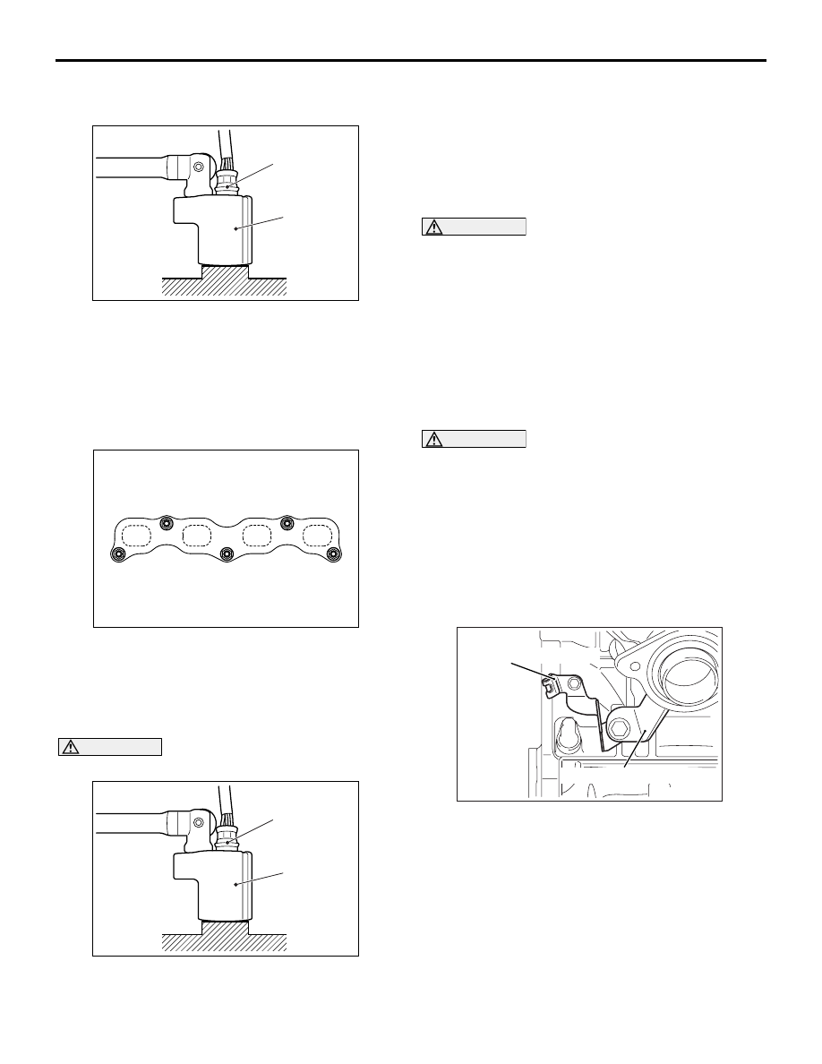
<<A>> OXYGEN SENSOR REMOVAL

AC301966

AB

MB991953

Oxygen sensor

Remove the connection and clamp of oxygen sensor 
connector, and then use special tool oxygen sensor 
wrench (MB991953) to remove the oxygen sensor.

INSTALLATION SERVICE POINTS

>>A<< EXHAUST MANIFOLD INSTALLA-
TION

AKB00880

1

2

AB

3

4

5

1. Tighten the exhaust manifold nut to the specified 

torque of 49 

± 5 N⋅m in the order shown in the 

illustration.

>>B<< OXYGEN SENSOR INSTALLATION

CAUTION

AC301966

AB

MB991953

Oxygen sensor

Do not use a sensor that has fallen down.

Tighten the oxygen sensor to the specified torque by 
using special tool oxygen sensor wrench 
(MB991953).

Tightening torque: 44 

± 5 Nm

>>C<< CRANK ANGLE SENSOR / O-RING 
INSTALLATION

CAUTION

• Do not apply a force such as torsion or twist 

to the O-ring during assembly of the sensor.

• Assemble the sensor, taking care not to give a 

shock to it.

• Do not use a sensor that has fallen down.

Tighten the crank angle sensor to the specified 
torque of 11 

± 1 N⋅m.

>>D<< EXHAUST MANIFOLD BRACKET 
INSTALLATION

CAUTION

The exhaust manifold gasket, washers and nuts 
must not be reused.
1. After temporarily tightening the exhaust manifold 

bracket with the installation bolts, check the 
exhaust manifold fastens securely to the cylinder 
block.

2. Tighten the cylinder block side bolt to the 

specified tightening torque.

Tightening torque: 41 

± 10 Nm

AKC00009

Crank angle sensor cover

Exhaust manifold bracket

AB

3. Tighten the exhaust manifold side bolt to the 

specified tightening torque.

Tightening torque: 56 

± 8 Nm

WATER HOSE AND PIPE

ENGINE OVERHAUL

11B-19

WATER HOSE AND PIPE

REMOVAL AND INSTALLATION

M1113032900722

AKC00005

12

13

1

14

15

16

11 ± 1 N·m

5

6

3

30 ± 9 N·m

4

2

7

8

9

10

11

AB

24 ± 3 N·m

28 ± 8 N·m

24 ± 3 N·m

24 ± 3 N·m

24 ± 3 N·m

24 ± 3 N·m

Removal steps 

1. Water hose

>>C<<

2. Coolant temperature sensor
3. Water outlet fitting
4. Outlet fitting gasket
5. Water inlet fitting

>>B<<

6. Thermostat

>>A<<

7. Thermostat housing
8. Thermostat housing gasket

>>A<<

9. Water pipe assembly
10. Water pipe gasket
11. O-ring
12. Water pump assembly
13. Water pump gasket
14. Engine hanger

15. Camshaft position sensor
16. O-ring

INSTALLATION SERVICE POINTS

>>A<< THERMOSTAT HOUSING / WATER 
PIPE ASSEMBLY INSTALLATION

Assemble the thermostat housing and water pipe, 
and temporarily tighten them to the cylinder head 
and water pump. Then tighten them to the specified 
torque of 24 

± 3 N⋅m.

Removal steps (Continued)

WATER HOSE AND PIPE

ENGINE OVERHAUL

11B-20

>>B<< THERMOSTAT INSTALLATION 

AK304916 AB

Jiggle Valve

Install the thermostat with the jiggle-valve facing 
almost straight upwards.

>>C<< COOLANT TEMPERATURE 
SENSOR INSTALLATION

CAUTION

Be careful not to give a shock, twist and the like 
to the resin mould with a tool during installation.

AK502544 AC

1. Apply an appropriate and minimum amount of 

sealant to the coolant temperature sensor, taking 
care not to allow sealant to squeeze out.

Specified sealant:

ThreeBond 1324N, Loctite 262 or equivalent

2. Tighten the coolant temperature sensor to the 

cylinder block to the specified torque of 30 

± 9 

N

⋅m.

OIL PAN AND TIMING CHAIN CASE

ENGINE OVERHAUL

11B-21

OIL PAN AND TIMING CHAIN CASE

REMOVAL AND INSTALLATION

M1113026301520

AKB00212

1

2

3

4

5

6

2.5 ± 0.4 N·m

11

10

3.0 ± 1.0 N·m   5.5 ± 0.5 N·m

48 ± 6 N·m

15

24 ± 4 N·m

8

7

39 ± 5 N·m

23 ± 6 N·m

12

10 ± 2 N·m

9

14 ± 2 N·m

13

10 ± 2 N·m

13 ± 1 N·m

10 ± 2 N·m

14

16

AC

31 ± 2 N·m

Removal steps 

1. Breather hose
2. PCV hose
3. PCV valve
4. O-ring
5. Oil filler cap
6. O-ring
7. Oil drain plug
8. Oil drain plug gasket

<<A>>

>>E<<

9. Oil filter

>>D<<

10. Cylinder head cover
11. Cylinder head cover gasket
12. Air compressor bracket

<<B>>

>>C<<

13. Oil pan
14. Engine support bracket

>>B<<

15. Front oil seal

<<C>>

>>A<<

16. Timing chain case

Removal steps (Continued)


Content   ..  264  265  266  267   ..