Mitsubishi Outlander (2013+). Manual - part 243
HOW TO READ WIRING DIAGRAMS
GENERAL <ELECTRICAL>
00E-7
WIRE COLOUR CODE
M1001008000195
Wire colours are identified by the following colour
codes.
Connector
connection
marking
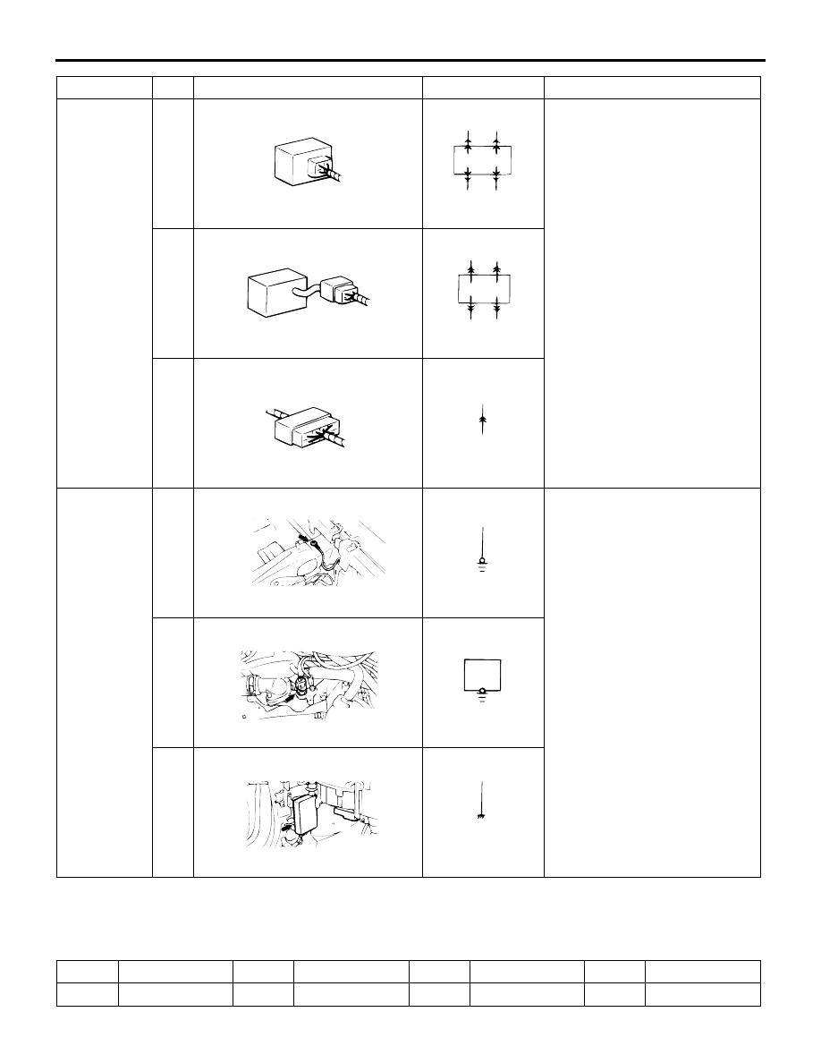
4
ACX01260 AD
Direct connection type
ACX01261
Connection between a device
and the harness is either by
direct insertion in the device
(direct connection type) or by
connection with a harness
connector furnished on the
device side (harness
connection type). The two types
are indicated as illustrated.
5
ACX01262 AD
Harness connection type
ACX01263
6
ACX01264AD
Intermediate connector
ACX01265
Earth
marking
7
AC208448
AB
Body earth
ACX01274
Earthing is either by body earth,
device earth or control unit
interior earth. These are
indicated as illustrated.
8
AC208449
AB
Device earth
ACX01276
9
AC208450
AB
Earth in control unit
ACX01278
Item
No.
Connector/Earthing
Symbol
Contents
Code
Wire colour
Code
Wire colour
Code
Wire colour
Code
Wire colour
B
Black
L
Blue
PU
Purple
V
Violet