Mitsubishi Outlander (2013+). Manual - part 241


  Index      Mitsubishi     Mitsubishi Outlander - service repair manual 2013 year


Search            


Content   ..  239  240  241  242   ..


Mitsubishi Outlander (2013+). Manual - part 241


TOWING AND HOISTING

GENERAL

00-46

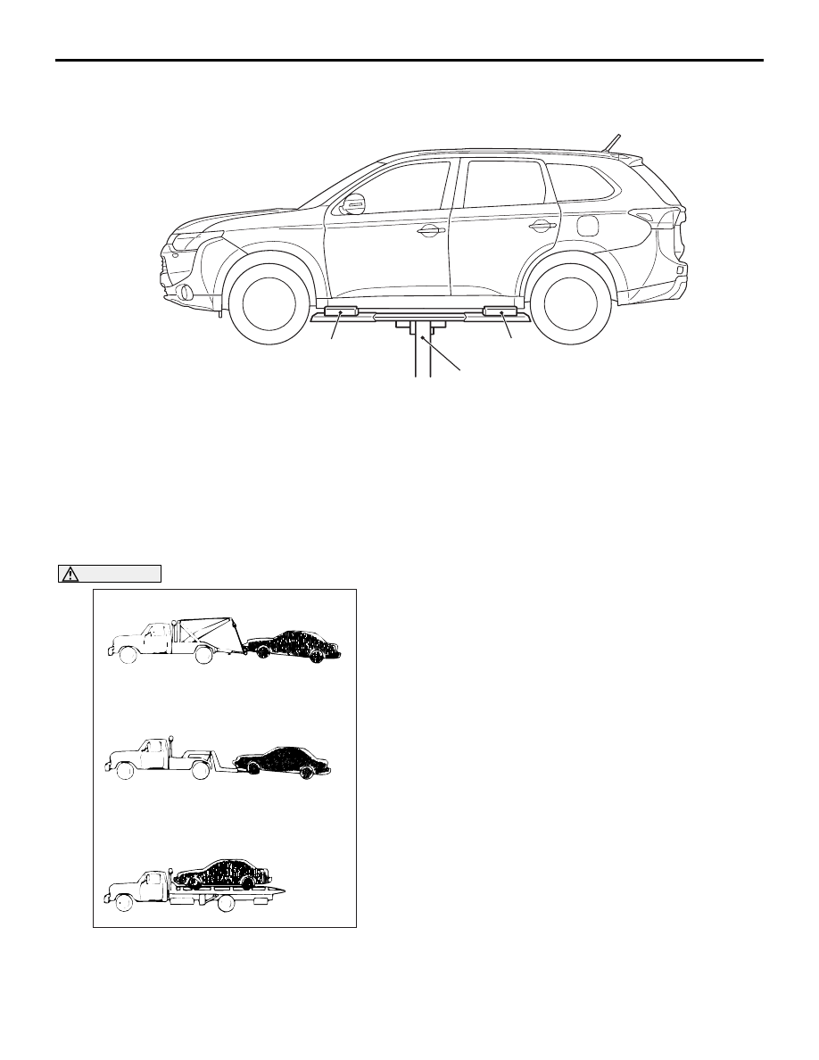
SUPPORT POSITIONS FOR A PLATE 
TYPE LIFT

ACB04350

Spacer

Spacer

Plate type lift

AB

Support the notch with a spacer (100-mm width, 
100-mm height and 200-mm depth).

TOWING AND HOISTING

M1001000800948

WRECKER TOWING RECOMMENDATION

FRONT TOWING PICKUP <2WD>

AC000070

SLING TYPE

WHEEL LIFT TYPE

FLAT BED TYPE

AJ

OK

OK

NO

CAUTION

This vehicle cannot be towed by a wrecker using 
sling-type equipment; as the bumper may 
become deformed. If this vehicle is towed, use 
wheel lift or flat bed equipment.
The vehicle may be towed on its rear wheels for 

extended distances provided the parking brake is 
released. It is recommended that vehicles be towed 
using the front pickup whenever possible.

TOWING AND HOISTING

GENERAL

00-47

FRONT TOWING PICKUP <4WD>

CAUTION

AC000070

NO

OK

NO

AL

SLING TYPE

WHEEL LIFT TYPE

FLAT BED TYPE

If only the front wheels or only the rear wheels 

are lifted for towing, the bumper will be dam-
aged.


In addition, lifting of the rear wheels causes 
the transfer case oil to flow forward, and may 
result in heat damage to the rear bushing of 
the transfer.

• The vehicle must not be towed by placing 

only its front wheels or only the rear wheels 
on a rolling dolly. This will result in deteriora-
tion of the viscous coupling causing the vehi-
cle to jump forward suddenly.

If this vehicle is towed, use flat bed equipment only.

REAR TOWING PICKUP

AC000071AH

SLING TYPE

WHEEL LIFT TYPE

FLAT BED TYPE

NO

OK

NO

CAUTION

Never lift the rear wheels, otherwise the vehicle 
becomes unstable while driving.

TOWING WHEN KEYS ARE NOT 
AVAILABLE 

When a locked vehicle must be towed and keys are 
not available, the vehicle may be lifted and towed 
from the front, provided the parking brake is 
released. If not released, the rear wheels should be 
placed on a tow dolly.

SAFETY PRECAUTIONS

The following precautions should be taken when tow-
ing the vehicle:

1. Do not lift or tow the vehicle by attaching to or 

wrapping around the bumper.

2. Any loose, protruding, or damaged parts such as 

hoods, doors, fenders, trim, etc. should be 
secured or removed prior to moving the vehicle.

3. Refrain from going under a vehicle when it is 

lifted by the towing equipment, unless the vehicle 
is adequately supported by safety stands.

4. Never allow passengers to ride in a towed vehi-

cle.

5. Local rules and regulations must be followed 

when towing a vehicle.

00E-1

GROUP 00E

GENERAL 

<ELECTRICAL>

CONTENTS

HOW TO READ WIRING DIAGRAMS

00E-2

COMPOSITION AND CONTENTS OF WIRING 
DIAGRAMS . . . . . . . . . . . . . . . . . . . . . . . . . 

00E-2

HOW TO READ CONFIGURATION DIAGRAMS


 . . . . . . . . . . . . . . . . . . . . . . . . . . . . . . . . . . . . . .

00E-2

HOW TO READ CIRCUIT DIAGRAMS . . . . 

00E-4

MARKINGS FOR CONNECTOR AND EARTHING


. . . . . . . . . . . . . . . . . . . . . . . . . . . . . . . . . . . . . . 

00E-5

WIRE COLOUR CODE . . . . . . . . . . . . . . . . 

00E-7

ABBREVIATION SYMBOLS . . . . . . . . . . . . 

00E-8

HOW TO READ WIRING DIAGRAMS

GENERAL <ELECTRICAL>

00E-2

HOW TO READ WIRING DIAGRAMS

COMPOSITION AND CONTENTS OF 
WIRING DIAGRAMS

M1001012800194

In each section, all specifications are listed, including optional specifications. Accordingly, some specifica-
tions may not be applicable for individual vehicles.

Section

Basic contents

Component 
locations

Locations are shown for each point of relays, ECUs, sensors, solenoid valves, 
inspection connectors, fusible links, fuses, etc. In the part’s lists, parts are listed in 
alphabetical order.

Configuration 
diagrams

Connector locations and harness wiring configurations on actual vehicles are 
illustrated.

Circuit diagrams

Circuits from power source to earth are shown completely, classified according to 
system. There is a main division into power source circuits and circuits classified by 
system.

• ETACS-ECU

The entire circuit for the ETACS-ECU is described, because only the part of the 
ETACS-ECU needed is normally shown in each circuit diagram.

• J/C

The internal circuits for all joint connectors are described, because only the part 
needed is shown in each circuit diagram.

• Power source circuits

Circuits from the battery to fusible link, fuse, ignition switch, etc are shown.

• Circuits classified by system

For each system, the circuits are shown from fuse to earth, excluding the power 
source sections.

HOW TO READ CONFIGURATION 
DIAGRAMS

M1001006400357

The wiring harness diagrams clearly show the connector locations and harness routings at each site on 
actual vehicles.


Content   ..  239  240  241  242   ..