Mitsubishi Outlander (2013+). Manual - part 234


  Index      Mitsubishi     Mitsubishi Outlander - service repair manual 2013 year


Search            


Content   ..  232  233  234  235   ..


Mitsubishi Outlander (2013+). Manual - part 234


PRECAUTIONS BEFORE SERVICE

GENERAL

00-18

PRECAUTIONS BEFORE SERVICE

ABOUT THE DESCRIPTION OF THE 
IGNITION SWITCH

M1001020400038

In this manual, the engine switch of vehicles with 
KOS and the ignition switch of vehicle without KOS 
are described as an ignition switch. (However, not 
"ignition switch", but "engine switch" is described in 
the GROUP 42B-KOS) 

Power supply mode by the engine switch operation

When the engine switch is pressed, the power supply 
mode changes according to the shift position and 
brake pedal operation state.

Shift position

Brake pedal operation

Power supply mode at engine switch operation

P position

Released

Every time the switch is pressed, the power supply mode 
changes from OFF to ACC to ON to OFF.

Depressed

While the power supply mode is OFF, the engine is started 
when the switch is pressed.

While the power supply mode is ACC, the engine is started 
when the switch is pressed.

While the power supply mode is ON, the engine is started 
when the switch is pressed.

Depressed or released

When the switch is pressed after the engine is started, the 
power supply mode is turned OFF (the engine stops).

Other than P 
position

Depressed or released

When the switch is pressed while the power supply mode is 
ACC, the power supply mode is turned ON.

When the switch is pressed while the power supply mode is 
ON, the power supply mode is turned to ACC.

When the switch is pressed after the engine is started, the 
power supply mode is turned to ACC.

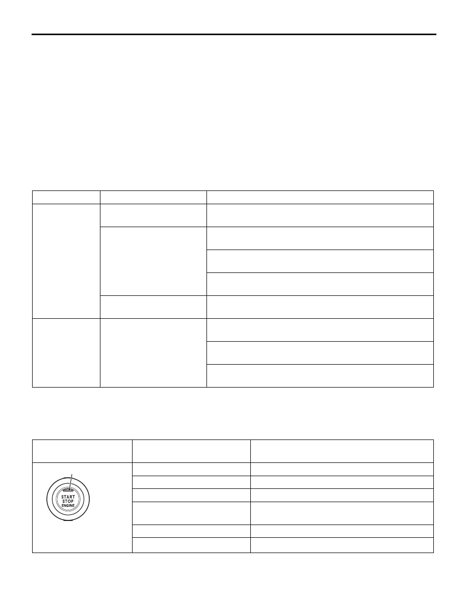
ENGINE SWITCH INDICATOR

Check that the engine switch indicator is switched as 
follows in each power supply mode and when an 
error is detected.

INDICATOR

Power supply mode and at 
error detection

INDICATOR

AC904994AB

Indicator

OFF

Extinguished

ACC

Illuminated in orange

ON

Illuminated in green

ON (after engine start)

Extinguished at 3 seconds after the engine is 
started

System error

Flashes in orange

Special operation mode 

*

Flashes in green (when ACC and ON only)

NOTE: 

*

: The special operation mode indicates that 

OSS-ECU is brand new.

PRECAUTIONS BEFORE SERVICE

GENERAL

00-19

SUPPLEMENTAL RESTRAINT SYSTEM 
(SRS)

M1001011601662

SRS AND SEAT BELT WITH PRE-TEN-
SIONER

CAUTION

Items to review when servicing SRS:

1. Be sure to read GROUP 52B 

 Supplemental 

Restraint System (SRS). For safe operation, 
please follow the directions and heed all 
warnings.

2. Wait at least 60 seconds after disconnecting 

the battery cable before doing any further 
work. The SRS system is designed to retain 
enough voltage to deploy the air bag even 
after the battery has been disconnected. Seri-
ous injury may result from unintended air bag 
deployment if work is done on the SRS sys-
tem immediately after the battery cable is dis-
connected.

3. Warning/Caution labels must be heeded when 

servicing or handling SRS components. 
Warning labels can be found in the following 
locations. (Refer to WARNING/CAUTION 
LABELS .)

4. Always use the designated special tools and 

test equipment.

5. Store components removed from the SRS in a 

clean and dry place. The air bag module 
should be stored on a flat surface and placed 
so that the pad surface is facing upward. Do 
not place anything on top of it.

6. Never attempt to disassemble or repair the 

SRS components (SRS-ECU, air bag module 
and clock spring).

7. Whenever you finish servicing the SRS, check 

the SRS warning lamp operation to make sure 
that the system functions properly.

8. Be sure to deploy the air bag before dispos-

ing of the air bag module or disposing of a 
vehicle equipped with an air bag (Refer to 
GROUP 52B 

 Air Bag Module Disposal Pro-

cedures).

Observe the following when carrying out opera-
tions on places where SRS components are 
installed, including operations not directly 
related to the SRS air bag.

1. When removing or installing parts, do not 

allow any impact or shock to the SRS compo-
nents.

2. If heat damage may occur during paint work, 

remove the SRS-ECU, the air bag module, 

clock spring, the front impact sensor, the side 
impact sensor, and the seat belt pre-ten-
sioner.

• SRS-ECU, air bag module, clock spring, 

front impact sensor, the side impact sen-
sor: 93 

°C or more

• Seat belt pre-tensioner: 90 °C or more

VEHICLES WITH AIR CONDITIONER

M1001011300088

CAUTION

Never start the engine with the refrigerant system 
empty as it will damage the A/C compressor.

PRECAUTIONS BEFORE SERVICE

GENERAL

00-20

MULTI USE TESTER (M.U.T.-III) SUB 
ASSEMBLY

M1001012400572

AC305090

MB991910

MB991826

MB991911

MB991825

MB991824

MB991827

AJ

Do not use

Vehicle communication interface (V.C.I.)

M.U.T.-III main harness A

M.U.T.-III USB cable

M.U.T.-III main harness B

M.U.T.-III adapter harness

M.U.T.-III trigger harness

MULTI USE TESTER (M.U.T.-III) 
sub assembly

ACB05419

MB992745

MB992746

MB992744

MB992747

MB992748

AB

Do not use

Vehicle communication interface-Lite 
(V.C.I.-Lite)

V.C.I.-Lite main harness A

V.C.I.-Lite USB cable short

V.C.I.-Lite USB cable long

V.C.I.-Lite main harness B

MULTI USE TESTER (M.U.T.-III)

• Both the special tool V.C.I. (MB991824) and the 

special tool V.C.I.-Lite (MB992744) can be used.

CAUTION

For the V.C.I., use MB991827 and MB991910. For 
the V.C.I.-Lite, use MB992745, MB992747 and 
MB992748.

• Refer to the "M.U.T.-III OPERATION MANUAL" 

for instructions on handling the M.U.T.-III.

PRECAUTIONS BEFORE SERVICE

GENERAL

00-21

CAUTION

Turn the ignition switch to the "LOCK" (OFF) 
position before connecting or disconnecting the 
M.U.T.-III.

ACB05017

MB992747, MB992748, MB991827

MB992744, MB991824

AB

MB992745, MB991910

Diagnosis connector

Connect the M.U.T.-III to the diagnosis connector as 
shown in the illustration.

SERVICING ELECTRICAL SYSTEM

M1001011900314

CAUTION

Before connecting or disconnecting the negative 
(

) cable, be sure to turn off the ignition switch 

and the lighting switch (If this is not done, there 
is the possibility of semiconductor parts being 
damaged).

AC300693

Before replacing a component related to the electri-
cal system and before undertaking any repair proce-
dures involving the electrical system, be sure to first 
disconnect the negative (

−) cable from the battery in 

order to avoid damage caused by short-circuiting.

HOW TO SHIFT LOCK FORCED RELEASE

M1001018100290

If the shift lever cannot be moved from the P position 
due to discharged battery or similar reasons, release 
the shift lock by observing the procedure below.

ACB05531AB

Remove the cover as shown, then insert a straight 
blade (or flat-tipped screwdriver) into the shift lock 
release hole, and move the selector lever while 
pressing the blade down.

HOW TO PERFORM CHASSIS NUMBER (CHASSIS NO.) WRITING FOR ENGINE-ECU, 
KOS-ECU AND ETACS-ECU

M1001011400814

Follow the procedure below to register the Chassis No. of the ETACS-ECU and the Keyless Operation Sys-
tem (KOS).

Chassis No. is stored in the engine-ECU, ETACS-ECU, and the KOS-ECU. If the Chassis No. is improperly 
erased, the engine warning lamp or the keyless operation system warning indicator illuminates, and the diag-
nosis code is displayed. When the engine-ECU, ETACS-ECU, and the KOS-ECU are replaced, follow the 
procedure below to write the Chassis No.


Content   ..  232  233  234  235   ..