Mitsubishi Outlander (2013+). Manual - part 224


  Index      Mitsubishi     Mitsubishi Outlander - service repair manual 2013 year


Search            


Content   ..  222  223  224  225   ..


Mitsubishi Outlander (2013+). Manual - part 224


SYSTEM OPERATION

CONTROLLER AREA NETWORK (CAN)

54C-4

• With CAN bus, the terminal resistors are incorpo-

rated in ECU. Resistors with approximately 120 
Ω is used for the dominant ECU.

NOTE: 

.

Dominant ECU: ETACS-ECU, engine ECU 
and Combination meter.

Non-dominant ECU: ECU and sensor on CAN 
network, excluding ETACS-ECU, engine ECU 
and Combination meter.

• To the CAN bus line, ECU, sensor, and diagnosis 

connector are connected as follows for each net-
work.

CAN-C

• ETACS-ECU

• Steering wheel sensor

• 4WD-ECU <4WD>

• SRS-ECU

• ABS-ECU <vehicles without ASC> or 

ASC-ECU <vehicles with ASC>

• CVT-ECU

• EPS-ECU 

• Diagnosis connector

• Engine-ECU

CAN-C-Mid

• ETACS-ECU

• OSS-ECU <vehicles with OSS>

• A/C-ECU

• KOS-ECU <vehicles with KOS>

• Radio and CD player <vehicles with radio and 

CD player>

• Electric tailgate control unit <vehicles with 

electric tailgate>

• CAN box unit <vehicles with MMCS>

• Corner sensor/back sensor-ECU <vehicles 

with reversing sensor system>

• Combination meter

SYSTEM OPERATION

M2542000300506

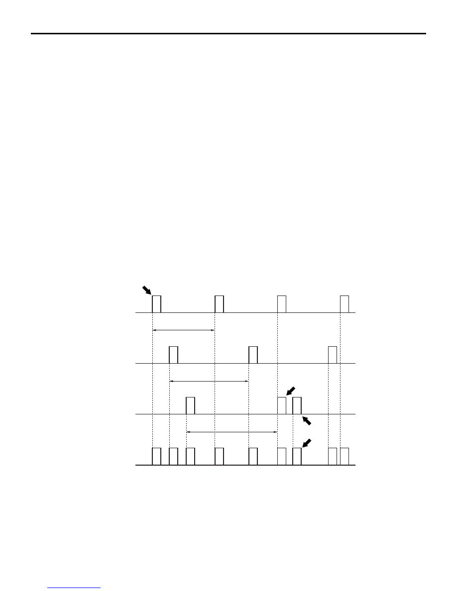
The CAN communication system is described below.

• Each ECU communicating with CAN periodically 

sends several sensors’ information on CAN bus 
as data frame (called periodical sending data). 
For further details, consult the data frame section.

• ECUs requiring data on CAN bus can receive 

data frames sent from each ECU simultaneously.

• The data sent from each ECU conducting CAN 

communication is transmitted at 0.01 

− 1 sec 

interval depending on necessity of data.

NOTE: In the figure above, the data frame A is trans-

mitted in "a" intervals, while the data frames B 
and C are transmitted at intervals "b" and "c," 
respectively.

• A single ECU transmits multiple data frames.

AC206267

ECU-1

A

A

A

A

B

B

B

C

C

A

B

Interval "a"

Interval "b"

Interval "c"

C

C

C

B

B

A

A

A

ECU-2

ECU-3

CAN bus

Data frames

AC206267AB

Transmission 
suspended by 
mediation

Re-
transmission

Downloaded from 

www.Manualslib.com


manuals search engine


SYSTEM OPERATION

CONTROLLER AREA NETWORK (CAN)

54C-5

• When data frames conflict with one another 

(when plural ECUs transmit signals simultane-
ously), data is prioritised for transmission by 
mediation, therefore, plural data frames are not 
sent simultaneously. For further details, consult 
the mediation section.

• Data is transmitted not by the conventional volt-

age-using method but by voltage potential differ-
ence. For further details, consult the section on 
CAN bus voltage transformation  .

• Reliability of each ECU transmitting signals via 

CAN communication is secured by several error 
detection and recovery processes. For further 
details, consult the sections on error detection 
and system recovery.

• For major communication signals (transmitting 

signals) among ECUs.

MEDIATION

Because each ECU transmits data independently on 
the CAN bus, there are cases of data collision when 
multiple data frames that ECUs attempt to transmit 
simultaneously (if multiple ECUs transmit at nearly 
the same moment). At this moment, processing of 
the ECUs attempting transmission is performed in 
the following way.

1. Data frame with high priority is transmitted first 

according to ID codes memorized in data frames.

2. Transmission of low-priority data (data frames) is 

suspended by the issuing ECUs until the bus 
clears (when no transmission data exists on the 
CAN bus).

NOTE: If the suspended state continues for a spe-

cific time, new data (data frame content) is cre-
ated and sent.

3. ECU containing suspended data frames trans-

mits the data when the bus becomes available.

NOTE: There is enough capacity on the CAN bus, 
which never prevents data frames from being sent.

VOLTAGE TRANSFORMATION ON THE CAN BUS

Data frame transmission through the CAN bus line 
involves voltage transformation (for output signals) in 
the distinctive CAN profile as follows. The ECU 
transmitting through the CAN_H and CAN_L bus 
lines sends 2.5 

− 3.5 V signals to the CAN_H side 

and 2.5 

− 1.5 V signals to the CAN_L side. The 

receiving ECU reads the data from the CAN_H and 
CAN_L potential difference. "Recessive" refers to the 
state where both CAN_H and CAN_L are under the 
2.5 V state, and "Dominant" refers to the state where 

CAN_H is under the 3.5 V state and CAN_L is under 
the 1.5 V state. By transformation mainly to 2.5 V, 
even in cases when voltage is rendered 0 from faulty 
earthing or the like (causing a problem of an approxi-
mate 0.5 voltage increase on the communications 
line), communication can be continued uninter-
rupted. Employing dual communications lines 
improves reliability to prevent the presence of noise, 
compared to the conventional communication 
method.

AC204753

Voltage 
transformation 
in CAN_L

State: 

Logical value:

Recessive

Recessive

Dominant

3.5 V

2.5 V

1.5 V

0

1

AE

Voltage 
transformation 
in CAN_H

Downloaded from 

www.Manualslib.com


manuals search engine


SELF-DIAGNOSIS

CONTROLLER AREA NETWORK (CAN)

54C-6

DATA FRAMES

The data frame, which is sent from each ECU (or 
sensor) to the CAN bus line, consists of the fields 
bellow.

SOF (Start of Frame)

• Indicates the start of the frame

ID (Identifier) region

• Identifies the data content while specifying prior-

ity rank in case of mediation

Control region

• Specifies the frame type, data length, etc.

Data region

• Values used for data control, etc.

CRC (Cyclic Redundancy Check) region

• Region where to check for errors in sent data. 

The transmitting ECU calculates data regions by 
applying prescribed operations and stores the 
results. The receiving ECU detects erroneous 
communication by comparing the CRC region 
with the data region.

ACK (Acknowledge) region

• Region where to conform the reception of sent 

data

EOF (End of Frame)

• Indicates the end of the frame

ERROR DETECTION AND RECOVERY

CAN protocol secures its reliability of communication 
by providing several error detection function such as 
CRC shown in data frame, and the recovery function 
(recovery is performed by resending, from abnormal 
state such as transmission errors). If an error is 
detected but it is not resolved even after recovery, 
communication is stopped. This state is called "Bus 
Off."

SELF-DIAGNOSIS

M2542000400428

• CAN self-diagnosis is performed by each ECU 

connected to the CAN bus.

• Diagnosis codes related to communication are 

named with the capital letter U, and are called 
"U-codes."

• A summary of the CAN self-diagnosis system is 

presented below.

TIME-OUT

Each ECU transmits data frames periodically. If the 
data frame is not received within the specified period, 
the intended receiving ECU transmits a diagnosis 
code indicating communication time-out for the ECU 
that failed to transmit.

FAILURE DATA

When the transmitting ECU detects failure of a sen-
sor directly connected to it, this is the pertinent data 
used to inform the ECU.

AC404606

SOF

EOF

ID region

CRC region

ACK 

region

Control 

region

Data region

Data Frames

AB

Downloaded from 

www.Manualslib.com


manuals search engine


CAN BUS DIAGNOSTICS

CONTROLLER AREA NETWORK (CAN)

54C-7

CAN BUS DIAGNOSTICS

M2542000500339

As ECUs are connected via CAN bus (including 
M.U.T.-III), always diagnose CAN bus to confirm its 
normality when inspecting. When the CAN bus diag-
nosis is carried out, the M.U.T.-III will monitor the 
mutual communication status of the ECUs and then 
display a current status of the CAN bus on its screen.

Downloaded from 

www.Manualslib.com


manuals search engine


Content   ..  222  223  224  225   ..