Mitsubishi Outlander (2013+). Manual - part 222


  Index      Mitsubishi     Mitsubishi Outlander - service repair manual 2013 year


Search            


Content   ..  220  221  222  223   ..


Mitsubishi Outlander (2013+). Manual - part 222


GENERAL INFORMATION

LOCAL INTERCONNECT NETWORK (LIN)

54B-2

GENERAL INFORMATION

M2545600100019

LIN refers to "Local Interconnect Network," which is a 

serial multiplex communication protocol

*

 adminis-

trated by LIN consortium. A communication circuit 
employing the LIN protocol connects each ECU, and 
switch and sensor data can be shared among ECUs, 
which enables more reduction in wiring.

NOTE: 

*

: The regulations that have been decided in 

detail, from software matters such as the necessary 
transmission rate for communication, the system, 
data format, and communication timing control 
method to hardware matters such as the harness 
type and length and the resistance values.
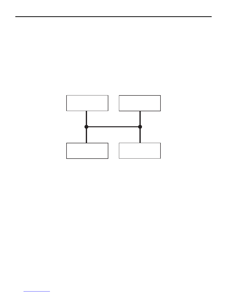
STRUCTURE

M2545600200395

Master and slave ECUs are connected to the LIN 

bus lines. The master ECU is the ETACS

*

-ECU, and 

the slave ECUs are the column switch (col-
umn-ECU), the sunroof-ECU <vehicles with sunroof> 
and the lighting control sensor <vehicles with lighting 
control sensor>. The master ECU requests these 
slave ECUs to communicate each other via commu-
nication lines.

NOTE: 

*

: ETACS (Electronic Time and Alarm Control 

System)

AC608956AD

ETACS-ECU

Column switch
(column-ECU)

Sunroof-ECU
<Vehicles with
sunroof>

Slave ECU

Slave ECU

Slave ECU

Master ECU

LIN bus line

Lighting control sensor 
<Vehicles with
 lighting control sensor>

Downloaded from 

www.Manualslib.com


manuals search engine


SYSTEM OPERATION

LOCAL INTERCONNECT NETWORK (LIN)

54B-3

SYSTEM OPERATION

M2545600300132

LIN communication system is described below:

• The master ECU performs the master tasks and 

slave tasks, and the slave ECUs perform the 
slave tasks.

• When the master ECU performs a master task, 

the header frame which stores information to call 
certain slave tasks (ECU) is transmitted at regular 
intervals.

• When the master ECU and slave ECU perform a 

slave task, the ECU called by the header frame 
transmits the response frame which stores data 
used for control.

• A header and response collectively are called as 

a message frame, and the communication 
method that uses the message frame is called as 
the frame communication.

• Basically, the communication data is used with 

some blocks of 10-bit data group which includes 
one start bit and one stop bit (byte field) arranged 
in order.

AC506324

AC506324

Master ECU

AE

Slave ECU

Slave ECU

Slave task A

Slave task B

Master task

Slave task D

Slave task C

LIN bus line

State of message on LIN bus line

<Master task>

<

Slave task

>

Response

Slave task D

Time

Header

Transmits the header 
at regular intervals.

Transmits the response
to suit the header

Byte field

Logical value:

1

0

Start bit

Stop bit

Data bit

1 byte

Slave task A

Slave task C

Slave task B

Response

Header

Response

Header

Response

Header

Downloaded from 

www.Manualslib.com


manuals search engine


SYSTEM OPERATION

LOCAL INTERCONNECT NETWORK (LIN)

54B-4

VOLTAGE VARIATION OF LIN BUS LINE

When each ECU sends or receives signals, LIN bus 
line voltage varies as follows:

• The voltage variation of LIN bus line (0 and 1 

combination as a logical value) ranging between 
battery voltage (recessive) and 0 V (dominant) is 
output (transmitted) as a control signal.

• When no communication is established, the LIN 

bus line remains recessive (battery voltage).

MESSAGE FRAME

A message frame consists of regions that include a 
synchronisation start region, identifier region, data 
region, and checksum region. A few bits of recessive 
data is used to separate the frame from each region.

AC309813

State:

Voltage variation 
of LIN bus line:

Logical value:

Recessive

Recessive

Dominant

Battery voltage

Earth level

1

0

AF

AC506907

Message frame

Header

Response

a

b

c

d

e

AD

d

d

a: Synchronisation start region

b: Synchronisation region

c: Identifier region

d: Data region

e: Checksum region

Logical value:

1 (Recessive)

0 (Dominant)

Frame

Region name

Description

Header

Synchronisation 
start region

A region that informs each ECU of the starting of header transmission 
by sending dominant signals for a given period of time.

Synchronisation 
region

A region that synchronises the transmission cycle of each ECU 
connected to the LIN bus line (the slave ECU matches its 
communication speed to that of the master ECU).

Identifier region

A region that stores an ID to call the slave ECU defined by the LIN 
protocol. The number of bytes for the data region is also defined in this 
region.

Downloaded from 

www.Manualslib.com


manuals search engine


SYSTEM OPERATION

LOCAL INTERCONNECT NETWORK (LIN)

54B-5

Response

Data region

A region to store the control data used by ECU that is called by the 
header

Checksum region

A region for checking errors in data content The sending-end ECU 
calculates data region value according to the specified computing 
equation, and the result is stored in this filed. The receiving-end ECU 
detects the transmission error based on the checksum filed value.

Frame

Region name

Description

Downloaded from 

www.Manualslib.com


manuals search engine


Content   ..  220  221  222  223   ..