Mitsubishi Outlander (2013+). Manual - part 172
ELECTRIC POWER STEERING
ELECTRIC POWER STEERING (EPS)
37-8
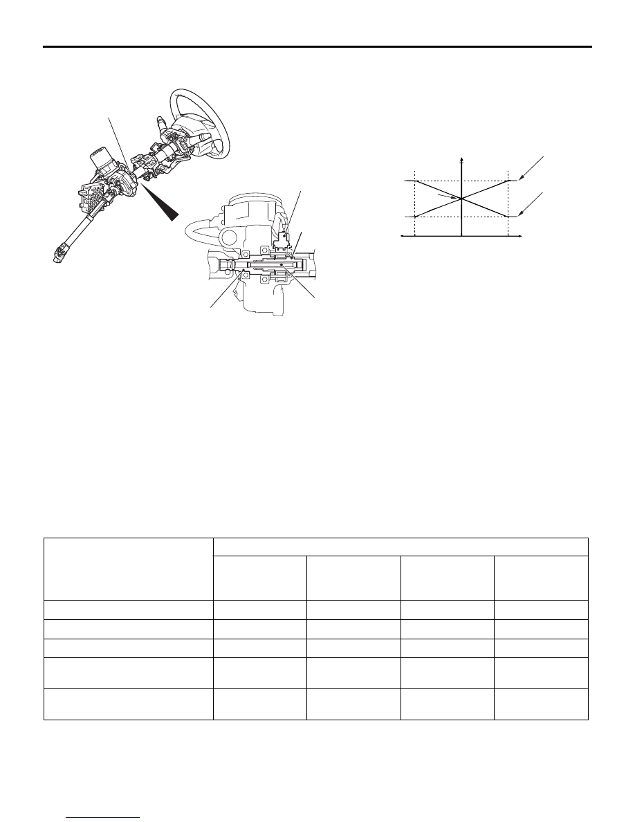
TORQUE SENSOR
M2370001600020
The torque sensor is mounted on the column shaft,
and detects the steering force. When the steering
wheel is turned, the phase relationship between the
input shaft and the lower shaft will be changed due to
distortion of the torsion bar. The torque sensor will
detect the distortion angle and send two voltage sig-
nals (main and sub) to the EPS-ECU in accordance
with it.
ELECTRIC POWER STEERING-ECU
(EPS-ECU)
M2370000800195
The EPS-ECU includes an input interface circuit, a
microprocessor, an output drive circuit, a power relay
and a motor line relay. It also integrates a self-diag-
nostic function, and illuminates the warning lamp on
the combination meter when a trouble occurs. At the
same time, it sends diagnosis code(s) to the diagno-
sis connector.
CAN communication
The EPS-ECU communicates with the other ECUs
and other units through CAN communication to con-
trol the steering system.
NOTE: Indicates items which send and receive data
through CAN communication.
ACB05508
AB
Torque sensor
Lower shaft
Torsion bar
Torque sensor
Input shaft
Output voltage (V)
Torque sensor characteristic chart
Neutral
Sub
Main
5
2.5
Input signals
Sent to
Engine-ECU
4WD-ECU
Combination
meter (via the
ETACS-ECU)
ETACS-ECU
Engine speed
•
−
−
−
Vehicle speed
•
−
−
−
Additional torque
•
Distance information (diagnosis
additional information)
−
−
•
−
Vehicle information (diagnosis
control)
−
−
−
•
manuals search engine