Mitsubishi Outlander (2013+). Manual - part 132


  Index      Mitsubishi     Mitsubishi Outlander - service repair manual 2013 year


Search            


Content   ..  130  131  132  133   ..


Mitsubishi Outlander (2013+). Manual - part 132


SENSOR

MULTIPOINT FUEL INJECTION (MPI)

13A-12

Accelerator pedal position sensor is integrated with 
accelerator pedal, and detects accelerator opening 
angle. Engine-ECU uses the output voltage of this 
sensor to control appropriate throttle valve opening 
angle and fuel injection volume. This accelerator 
pedal position sensor uses Hall IC and is a non-con-
tact type.

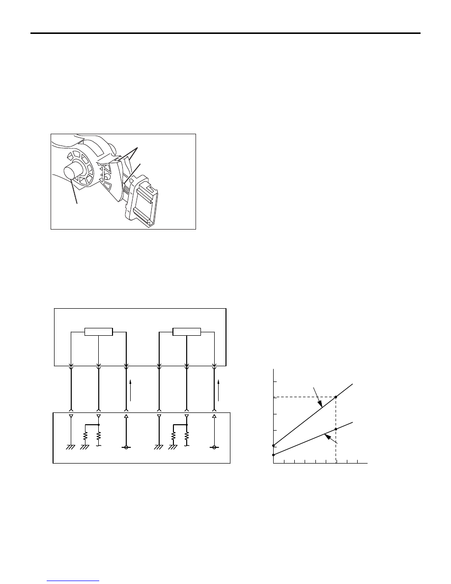
STRUCTURE AND SYSTEM

Accelerator pedal position sensor is composed of a 
permanent magnet fixed on the magnet carrier of the 
pedal shaft, Hall IC outputs voltage according to 
magnetic flux density and a stator that efficiently 
introduces magnetic flux from the permanent magnet 
to Hall IC.

Magnetic flux density at Hall IC is proportional to the 
output voltage. 
The accelerator pedal position sensor has 2 output 
systems 

− accelerator pedal position sensor (main) 

and accelerator pedal position sensor (sub), and the 
output voltage is output to engine-ECU. According to 
depression of the accelerator pedal, output voltage 
of the accelerator pedal position sensor (main) and 
accelerator pedal position sensor (sub) changes. 
This allows engine-ECU to detect the actual acceler-
ator pedal depression amount. Engine-ECU uses 
accelerator pedal position sensor (main) output volt-
age for appropriate throttle valve opening angle con-
trol and fuel injection volume control. Also, 
engine-ECU compares output voltage of the acceler-
ator pedal position sensor (main) and accelerator 
pedal position sensor (sub) to check for abnormality 
in sensor. The relationship between accelerator 
opening angle and output voltage of the accelerator 
pedal position sensor (main) and accelerator pedal 
position sensor (sub) is as shown in the figure below.

AK602570AB

Magnet

Pedal shaft

Hall IC

AK602211

5V

5V

5

4

3

2

1

0

AD

Accelerator pedal position sensor

Accelerator pedal
position sensor (main)

Accelerator pedal
position sensor (main)

Accelerator
pedal stroke

Accelerator pedal
position sensor (sub)

Accelerator pedal
position sensor (sub)

Hall IC

Hall IC

Full throttle
point 

Output voltage (V)

Engine-ECU

Downloaded from 

www.Manualslib.com


manuals search engine


SENSOR

MULTIPOINT FUEL INJECTION (MPI)

13A-13

When abnormality is detected

Engine-ECU compares output voltage of the acceler-
ator pedal position sensor (main) and accelerator 
pedal position sensor (sub) to check for abnormality 
in sensor. If the engine-ECU detects the abnormality, 
the emergency should be prevented by performing 
the fuel-safe control.

• When 1-system malfunctions

The engine-ECU should detect the amount of 

accelerator pedal depressed by only using the 
signal having no malfunctions. Depressing 
the accelerator pedal half way can perform 
the control. Performing the fuel cut can 
increase the engine rotation speed. 

• When 2-system malfunctions

The engine-ECU should cut the energization of 

the throttle valve control servo. At that time, 
the spring built in the throttle valve can slightly 
open the throttle valve. This allows the 
engine-ECU to control the engine output.

OXYGEN SENSOR

The oxygen sensor (front) is installed in the exhaust 
manifold. The oxygen sensor (rear) is installed in the 
exhaust front pipe. 
Oxygen sensor has a built-in heater to help early 
activation of the sensor. This allows feedback control 
of air-fuel ratio soon after engine start.

This sensor uses the oxygen concentration cell prin-
ciple of solid electrolyte (zirconia) and displays the 
property of sudden change in output voltage near 
theoretical air-fuel ratio. This property is used to 
detect oxygen density in exhaust gas. Feedback to 
engine-ECU allows it to judge whether air-fuel ratio is 
rich or lean compared to theoretical air-fuel ratio.
This allows engine-ECU precise feedback control to 
get theoretical air-fuel ratio with best cleaning effi-
ciency of 3-way catalytic converter.

AKB00595

Throttle
position
sensor

Main

Restrict or shut off
the operating

Main

Sub

Sub

Accelerator
pedal position
sensor

Engine-ECU

Fuel cut

Injector

Throttle valve
control servo

AB

AKB00751AB

Sensing 
area

Sensing 
area

Front

Rear

Downloaded from 

www.Manualslib.com


manuals search engine


SENSOR

MULTIPOINT FUEL INJECTION (MPI)

13A-14

CRANK ANGLE SENSOR

A crank angle sensor is installed on the exhaust side 
of the cylinder block. The crank angle sensor moni-
tors rotation of crankshaft sensing ring (36 teeth 
including 3 missing teeth) installed on the crankshaft 
and converts to voltage (pulse signal) that is output 
to engine-ECU. Engine-ECU uses crank angle sen-
sor's output pulse to detect crankshaft position.

The crank angle sensor uses a magnetic resistance 
element. When the vane of the crankshaft-sensing 
ring passes the front surface of the magnetic resist-
ance element, the flux from the magnet passes the 
magnetic resistance element. Thus, resistance of the 
magnetic resistance element increases. When the 
vane of the crankshaft-sensing ring does not pass 
the front surface of the magnetic resistance element, 

AK602576AB

From engine control relay

Oxygen sensor

Heater

Zirconia element

Engine-ECU

0.5V

AK602737AE

Crank angle
sensor

Crankshaft sensing ring
(36 teeth including 3 missing teeth)

AK602265AD

Crankshaft sensing ring

Crankshaft sensing ring

Vane

Vane

Magnetic resistance element

Magnetic resistance element

Magnet flux

Magnet flux

Downloaded from 

www.Manualslib.com


manuals search engine


SENSOR

MULTIPOINT FUEL INJECTION (MPI)

13A-15

the flux from the magnet does not pass the magnetic 
resistance element and the resistance decreases. 
The crank angle sensor converts this change in 
resistance of the magnetic resistance element to a 5 
V pulse signal and outputs it to engine-ECU.

INLET CAMSHAFT POSITION SENSOR

The inlet camshaft position sensor is installed on the 
inlet side of the cylinder head. The inlet camshaft 
position sensor monitors shape of the half-moon 
sensing portion and converts to voltage (pulse sig-
nal) that is output to engine-ECU. Upon receiving this 
output voltage, the engine-ECU effects feedback 
control to optimize the phase of the inlet camshaft. 
Also, engine-ECU uses a combination of the cam-
shaft position sensor output pulse signal and crank-
shaft position sensor output pulse signal to identify 
cylinders in the compression process.

The inlet camshaft position sensor uses a magnetic 
resistance element. When the camshaft position 
sensing portion passes the front surface of the mag-
netic resistance element, the flux from the magnet 
passes the magnetic resistance element. Thus, 
resistance of the magnetic resistance element 
increases. When the camshaft position sensing por-
tion does not pass the front surface of the magnetic 
resistance element, the flux from the magnet does 

AK602285AB

5V

5V

Crank angle sensor

Engine-ECU

Output signal

Magnetic resistance element

AK602738AB

Camshaft

Sensing portion

Camshaft position sensor

AK602574AE

Camshaft position sensing portion

Camshaft position sensing portion

Magnetic resistance element

Magnetic resistance element

Magnet flux

Magnet flux

Downloaded from 

www.Manualslib.com


manuals search engine


Content   ..  130  131  132  133   ..