Mitsubishi Outlander (2013+). Manual - part 89
AERO PARTS
EXTERIOR
51-5
AERO PARTS
M2510003001348
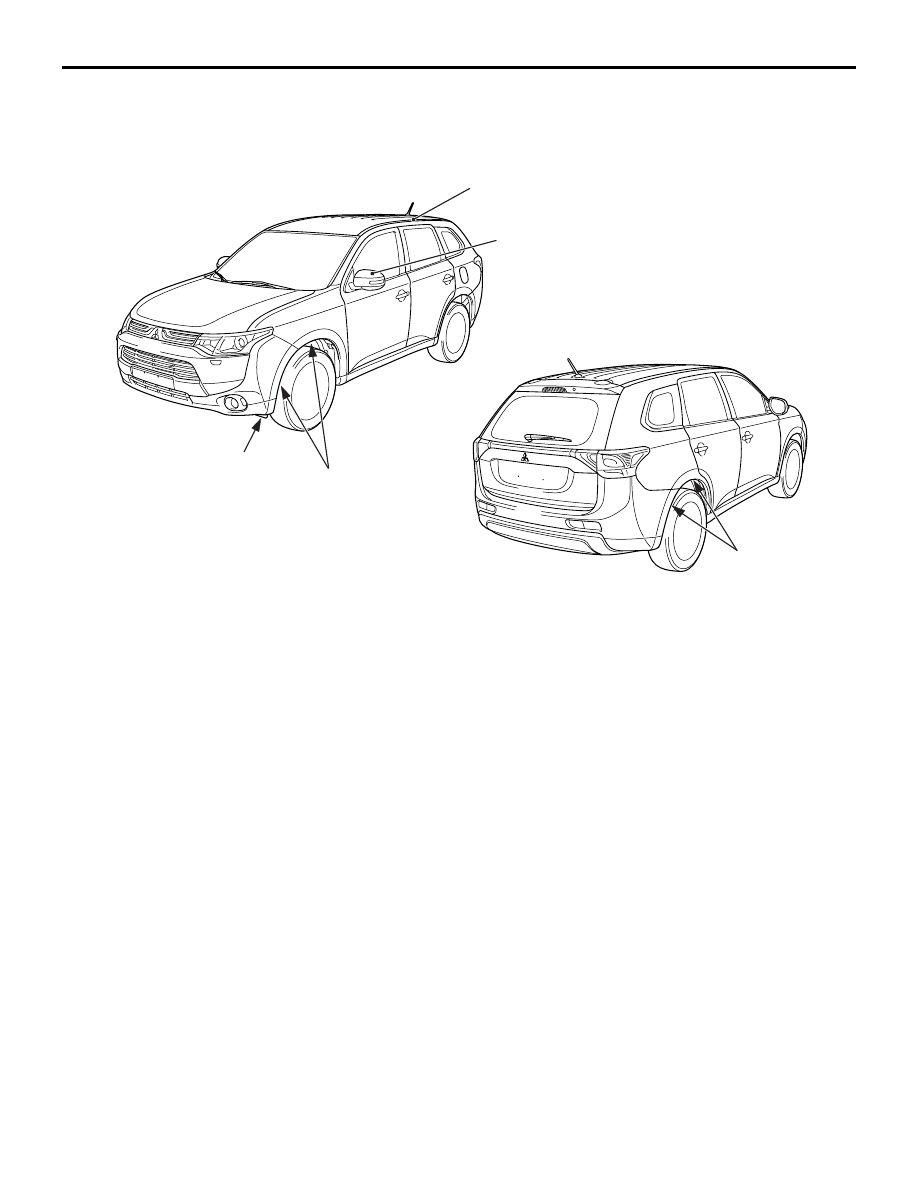
CONSTRUCTION DIAGRAM
Aerodynamic performance has been improved by the
optimised shape of the following parts.
• Front side air dam: Refer to .
• Overfender shape: Overfender shape from the
front bumper to the fender and from the quarter
panel to the rear bumper keeps the off-road vehi-
cle image as an SUV, at the same time the opti-
mised shape of the related parts improves
aerodynamic performance.
• Roof drip moulding: Groove in the roof moulding
is eliminated in order to reduce wind noise and
aerodynamic drag.
• Door mirror
ACC00450
AB
Door mirror
Overfender
shape
Overfender
shape
Roof drip moulding
Front side air dam