Mitsubishi Outlander (2003+). Manual - part 506
INPUT SIGNAL PROCEDURES
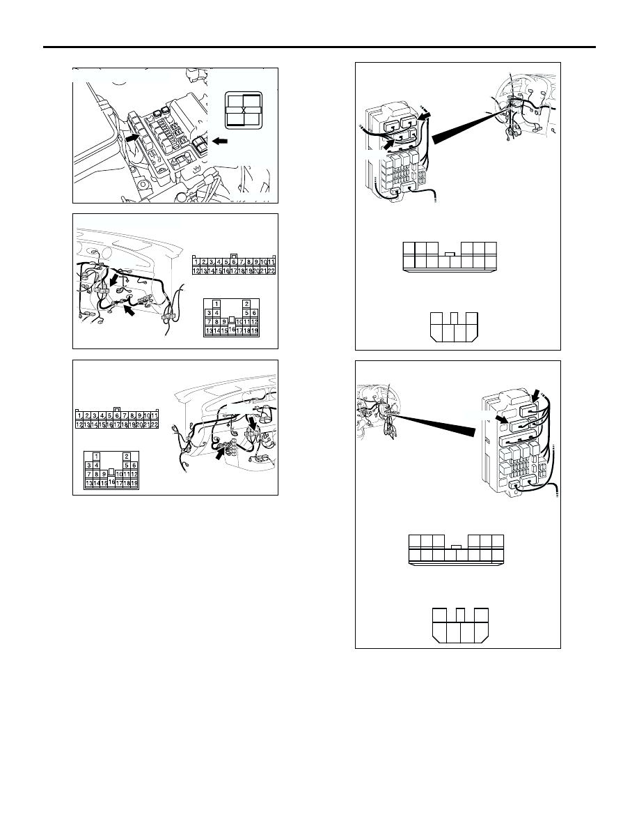
SMART WIRING SYSTEM (SWS) NOT USING SWS MONITOR
54B-313
NOTE:
Prior to the wiring harness inspection, check A/T
control relay connector B-16X, joint connector C-16,
intermediate connector C-106 and junction block
connectors C-202 and C-203, and repair if
necessary.
•
Check the power supply line to the ignition switch
(IG1) for open circuit.
Q: Is the check result normal?
AC301515 AG
Connector: B-16X
1
3
2
4
Front of
vehicle
Relay box side
AC308718
Connectors: C-16, C-106 <LHD>
AK
C-16
C-106
C-16
C-106
AC308735
Connectors: C-16, C-106
<RHD>
AM
C-16
C-106
C-16
C-106
AC308721
Connectors: C-202, C-203
AC
Junction block (Front view)
C-202
C-203
Harness side
C-203
C-202
4
6 5
3
2
1
10
1
6
14
5
12
13
4
11
7
2
3
8
9
<LHD>
Harness side
AC308773
Connectors: C-202, C-203
AC
Junction block (Front view)
C-202
C-203
Harness side
C-203
C-202
4
6 5
3
2
1
10
1
6
14
5
12
13
4
11
7
2
3
8
9
<RHD>
Harness side