Mitsubishi Outlander (2003+). Manual - part 504
INPUT SIGNAL PROCEDURES
SMART WIRING SYSTEM (SWS) NOT USING SWS MONITOR
54B-305
DIAGNOSTIC PROCEDURE
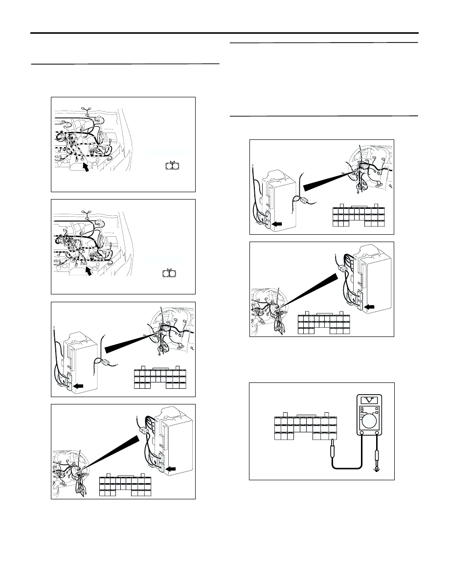
Step 1. Connector check: B-114 <2000 or 2400-
L.H. drive vehicles> back-up lamp switch
connector and C-220 ETACS-ECU connector
Q: Is the check result normal?
YES :
Go to Step 2.
NO :
Repair the defective connector.
Step 2. Check the back-up lamp switch
Check the back-up lamp switch (Refer to GROUP
22B
−
Transmission
Q: Is the check result normal?
YES :
Go to Step 3.
NO :
Replace the inhibitor switch.
Step 3. Measure the voltage at the C-220
ETACS-ECU connector.
(1) Disconnect the connector, and measure at the
wiring harness side.
(2) Ignition switch: ON
(3) Shift position: R position
(4) Voltage between C-220 ETACS-ECU connector
terminal No.39 and body earth
OK: System voltage
AC308694
2 1
AD
Connector: B-114 <2000 (LHD)>
Harness side
B-114(B)
AC308708
2 1
AE
Connector: B-114 <2400 (LHD)>
Harness side
B-114(B)
AC308722
Connector: C-220
Junction block (Rear view)
AF
Harness side
28
37
43
29
44
38
23
32
41
24
25
26
27
34
42
3635
33
21
22
30
39
40
31
<LHD>
AC308776
Connector: C-220
Junction block (Rear view)
AD
Harness side
28
37
43
29
44
38
23
32
41
24
25
26
27
34
42
3635
33
21
22
30
39
40
31
<RHD>
AC308722
Connector: C-220
Junction block (Rear view)
AF
Harness side
28
37
43
29
44
38
23
32
41
24
25
26
27
34
42
3635
33
21
22
30
39
40
31
<LHD>
AC308776
Connector: C-220
Junction block (Rear view)
AD
Harness side
28
37
43
29
44
38
23
32
41
24
25
26
27
34
42
3635
33
21
22
30
39
40
31
<RHD>
AC301541BA
Connector C-220
(Harness side)
28
37
43
29
44
38
23
32
41
24
25
26
27
34
42
3635
33
21
22
30
39
40
31