Mitsubishi Outlander (2003+). Manual - part 494
SYMPTOM PROCEDURES
SMART WIRING SYSTEM (SWS) NOT USING SWS MONITOR
54B-265
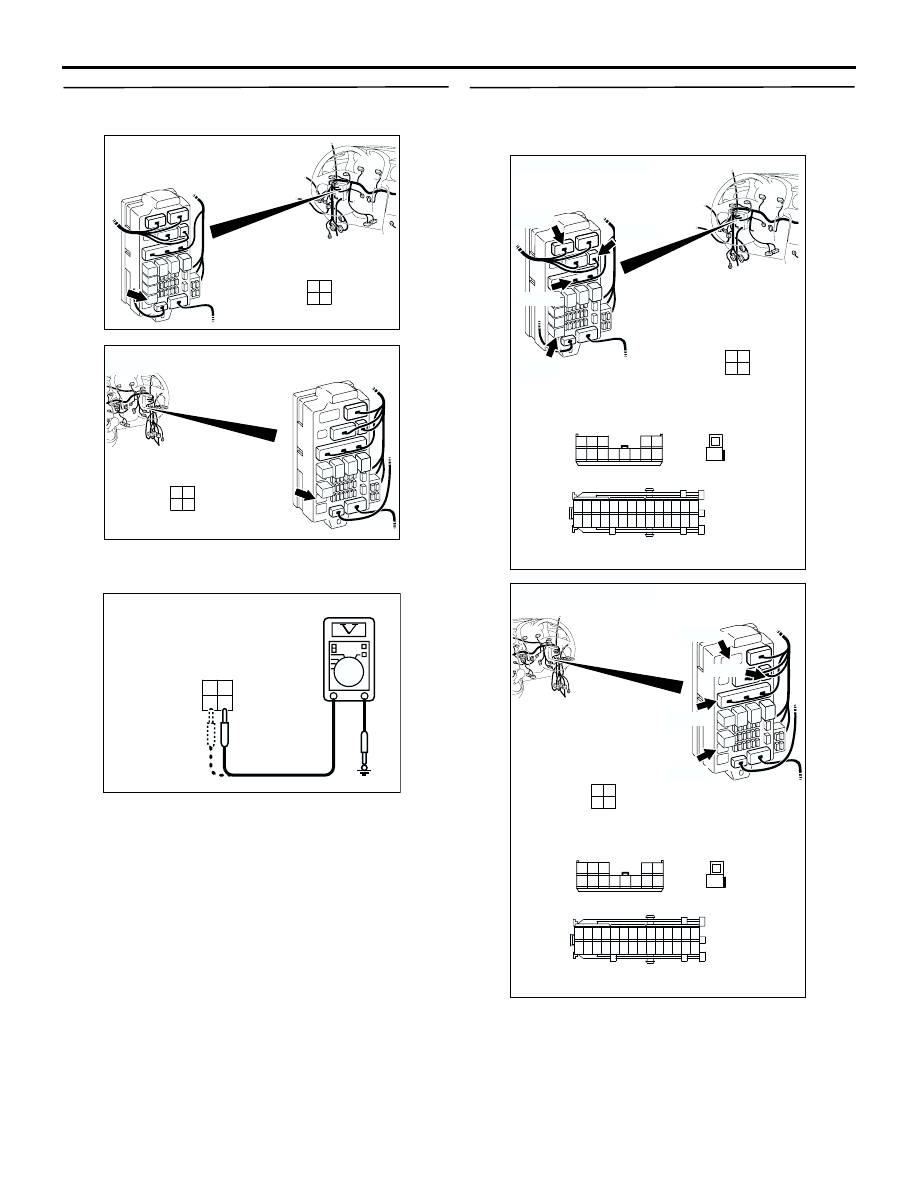
Step 5. Measure the voltage at the C-212 rear fog
lamp relay connector.
(1) Remove the rear fog lamp relay, and measure at
the relay box side.
(2) Check the voltage between the rear fog lamp
relay connector and body earth.
•
Voltage between C-212 rear fog lamp relay
connector terminal No.3 and body earth
•
Voltage between C-212 rear fog lamp relay
connector terminal No.4 and body earth
OK: System voltage
Q: Is the check result normal?
YES :
Go to Step 7.
NO :
Go to Step 6.
Step 6. Check the wiring harness between C-212
rear fog lamp relay connector (terminal Nos. 3
and 4) and the battery.
AC308720
Connector: C-212
AJ
3
1
2
4
Junction block (Front view)
Junction block side
<LHD>
AC308772
Connector: C-212
AI
3
1
2
4
Junction block (Front view)
Junction block side
<RHD>
AC301541 AR
Connector C-212
(Relay box side)
4
2 1
3
AC308721
Connectors: C-201, C-204, C-205, C-212
AH
Junction block (Front view)
C-201
Junction block side
C-205
C-204
C-212
21
7
16 15
17
18
20 19
1
2
3
4
5
6
23 22
24
25
28
26
27
9
8
10
11
14
12
13
C-205
3
1
2
4
C-212
Harness side
1
C-204
5 4 3
2 1
13121110 9 8 7 6
C-201
<LHD>
AC308773
Connectors: C-201, C-204, C-205, C-212
AI
Junction block (Front view)
C-201
Junction block side
C-205
C-204
C-212
21
7
16 15
17
18
20 19
1
2
3
4
5
6
23 22
24
25
28
26
27
9
8
10
11
14
12
13
C-205
3
1
2
4
C-212
Harness side
1
C-204
5 4 3
2 1
13121110 9 8 7 6
C-201
<RHD>