Mitsubishi Outlander (2003+). Manual - part 478


  Index      Mitsubishi     Mitsubishi Outlander - service repair manual 2003 year


Search            


Content   ..  476  477  478  479   ..


Mitsubishi Outlander (2003+). Manual - part 478


SYMPTOM PROCEDURES

SMART WIRING SYSTEM (SWS) NOT USING SWS MONITOR

54B-201

Step 2. Pulse check

Check the input signals below which are related to 
the windshield wiper.

OK: The MUT-II/III sounds or the voltmeter 
needle fluctuates. 

Q: Is the check result normal?

All the signals are received normally : 

Go to Step 

3.

The ignition switch (ACC) signal is not received. : 

Refer to inspection procedure N-1 "The 
ignition switch (ACC) signal is not received 

P.54B-298

."

Headlamp washer switch signal is not received. : 

Refer to inspection procedure N-5 "The 
column switch (headlamp washer switch) 
signal is not received 

P.54B-319

."

Step 3. Connector check: A-25 headlamp washer 
motor connector

Q: Is the check result normal?

YES : 

Go to Step 4.

NO : 

Repair the connector.

Step 4. Check the headlamp washer motor 
assembly.

Refer to GROUP 51 

 Headlamp washer 

P.51-45

.

Q: Is the check result normal?

YES : 

Go to Step 5

NO : 

Replace the headlamp washer motor.

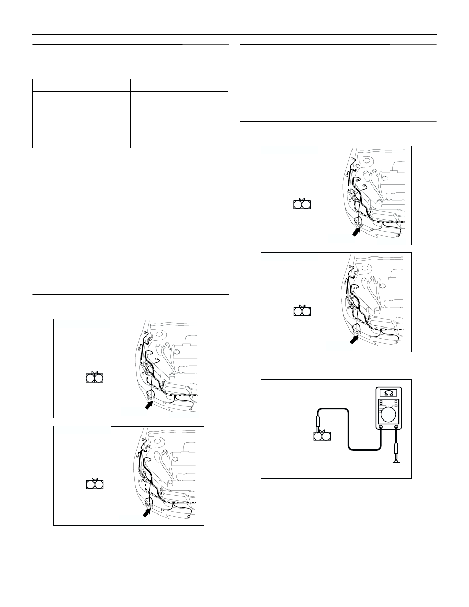
Step 5. Measure the resistance at the A-25 
headlamp washer motor connector.

(1) Disconnect the connector, and measure at the 

wiring harness side.

(2) Continuity between A-25 headlamp washer motor 

connector terminal No.2 and body earth

OK: 2

 or less

Q: Is the check result normal?

YES : 

Go to Step 7.

NO : 

Go to Step 6.

System switch

Check condition

Ignition switch (ACC)

When turned from the 
LOCK (OFF) position to 
the ACC position.

Headlamp washer switch When the switch is 

turned from off to on.

AC308677

Connector : A-25

AB

A-25(B)

2 1

A-25

Harness side

<LHD>

AC308684

Connector : A-25

AB

A-25(B)

2 1

A-25

Harness side

<RHD>

AC308677

Connector : A-25

AB

A-25(B)

2 1

A-25

Harness side

<LHD>

AC308684

Connector : A-25

AB

A-25(B)

2 1

A-25

Harness side

<RHD>

2 1

AC301725

Connector A-25
(harness side)

AB

SYMPTOM PROCEDURES

SMART WIRING SYSTEM (SWS) NOT USING SWS MONITOR

54B-202

Step 6. Check the wiring harness between A-25 
headlamp washer motor connector terminal No.2 
and body earth.

Check the earth wires for open circuit.

Q: Is the check result normal?

YES : 

The trouble can be an intermittent 

malfunction (Refer to GROUP 00 

 How to 

Cope with Intermittent Malfunction 

P.00-6

).

NO : 

Repair the wiring harness.

Step 7. Connector check: A-11X front-ECU 
connector

Q: Is the check result normal?

YES : 

Go to Step 8.

NO : 

Repair the connector.

Step 8. Measure the voltage at the A-11X 
front-ECU connector.

(1) Remove the front-ECU, and measure at the 

junction block side.

(2) Ignition switch: ACC

(3) Check the voltage between the A-11X front-ECU 

connector terminal No.3 and body earth.

OK: System voltage

Q: Is the check result normal?

YES : 

Go to Step 10.

NO : 

Go to Step 9.

AC308677

Connector : A-25

AB

A-25(B)

2 1

A-25

Harness side

<LHD>

AC308684

Connector : A-25

AB

A-25(B)

2 1

A-25

Harness side

<RHD>

AC301515 AD

Connector: A-11X

5

11

9

10

8 7 6

2

4 3

1

Relay box side

AC301515 AD

Connector: A-11X

5

11

9

10

8 7 6

2

4 3

1

Relay box side

5

11

9

10

8 7 6

2

4 3

1

AC301726

Connector A-11X
(Relay box side)

AB

SYMPTOM PROCEDURES

SMART WIRING SYSTEM (SWS) NOT USING SWS MONITOR

54B-203

Step 9. Check the wiring harness between A-11X 
front-ECU connector terminal No.3 and the 
fusible link (5).

Check the power supply line from the fusible link 
(5) for open circuit.

Q: Is the check result normal?

YES : 

The trouble can be an intermittent 

malfunction (Refer to GROUP 00 

 How to 

Cope with Intermittent Malfunction 

P.00-6

).

NO : 

Repair the wiring harness.

Step 10. Check the wiring harness between A-25 
headlamp washer motor connector terminal No.1 
and A-11X front-ECU connector terminal No.1.

Check the output line to headlamp washer motor 
for open circuit.

Q: Is the check result normal?

YES : 

Go to Step 11.

NO : 

Repair the wiring harness.

Step 11. Retest the system.

The headlamp washer should now work normally.

Q: Is the check result normal?

YES : 

The trouble can be an intermittent 

malfunction (Refer to GROUP 00 

 How to 

Cope with Intermittent Malfunction 

P.00-6

).

NO : 

Replace the front-ECU.

AC301515 AD

Connector: A-11X

5

11

9

10

8 7 6

2

4 3

1

Relay box side

AC301515 AD

Connector: A-11X

5

11

9

10

8 7 6

2

4 3

1

Relay box side

AC308677

Connector : A-25

AB

A-25(B)

2 1

A-25

Harness side

<LHD>

AC308684

Connector : A-25

AB

A-25(B)

2 1

A-25

Harness side

<RHD>

SYMPTOM PROCEDURES

SMART WIRING SYSTEM (SWS) NOT USING SWS MONITOR

54B-204

IGNITION KEY CYLINDER 
ILLUMINATION LAMP

INSPECTION PROCEDURE I-1: The ignition key cylinder illumination lamp does not 
illuminate/extinguish normally.

CAUTION

Whenever the ECU is replaced, ensure that the 
input and output signal circuits are normal.

COMMENTS ON TROUBLE SYMPTOM
The ETACS-ECU operates this function in 
accordance with the input signals below.

<Vehicles without keyless entry system>

Ignition switch (IG1)

Driver's door switch

<Vehicles with keyless entry system>

Ignition switch (IG1)

Key reminder switch

Driver's door switch

Interior lamp loaded signal

If this function does not work normally, these input 
signal circuit(s), the ignition key cylinder illumination 
lamp or the ETACS-ECU may be defective.

POSSIBLE CAUSES

Malfunction of the key reminder switch

Malfunction of the driver's door switch

Malfunction of the ignition key cylinder 
illumination lamp

Malfunction of the ETACS-ECU

Damaged harness wires and connectors

KEY CYLINDER
ILLUMINATION LAMP

KEY
REMINDER SWITCH

FUSIBLE
LINK

1

ETACS-ECU

Wire colour code
B : Black     LG : Light green     G : Green     L : Blue     W : White     Y : Yellow     SB : Sky blue
BR : Brown     O : Orange     GR : Gray     R : Red     P : Pink     V : Violet   

Ignition Key Cylinder Illumination Lamp Circuit


Content   ..  476  477  478  479   ..