Mitsubishi Outlander (2003+). Manual - part 434


  Index      Mitsubishi     Mitsubishi Outlander - service repair manual 2003 year


Search            


Content   ..  432  433  434  435   ..


Mitsubishi Outlander (2003+). Manual - part 434


DIAGNOSTIC TROUBLE CODE PROCEDURES

SMART WIRING SYSTEM (SWS) NOT USING SWS MONITOR

54B-25

Diagnosis code 13: Trouble related to the front-ECU or improper connection with the ETACS-ECU

CAUTION

Whenever the ECU is replaced, ensure that the 
power supply circuit, the earthing circuit and the 
communication circuit are normal.

Wire colour code
B : Black     LG : Light green     G : Green     L : Blue     W : White     Y : Yellow     SB : Sky blue
BR : Brown     O : Orange     GR : Gray     R : Red     P : Pink     V : Violet   

IGNITION 
SWITCH (IG2)

DIAGNOSIS 
CONNECTOR

ETACS-ECU

POWER 
SOURCE

FRONT-ECU

(FUSE     )

22

RELAY BOX

FRONT SIDE

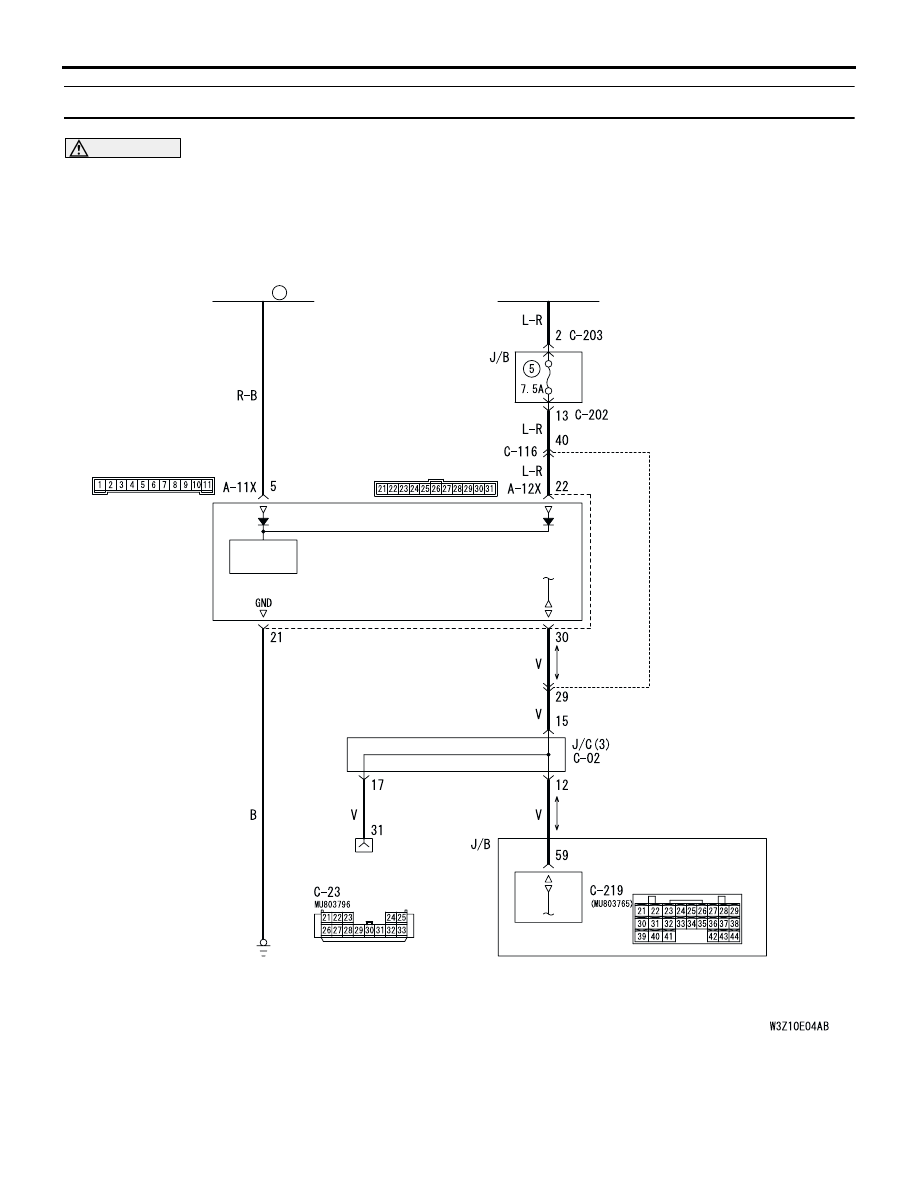
Front-ECU Power Supply and SWS Communication Circuit <LHD>

DIAGNOSTIC TROUBLE CODE PROCEDURES

SMART WIRING SYSTEM (SWS) NOT USING SWS MONITOR

54B-26

DIAGNOSIS CODE SET CONDITIONS
If the front-ECU has sent abnormal signal to the 
ETACS-ECU for consecutively 15 communication 
cycles (0.6 second), the diagnosis code will be set. If 
the front-ECU has sent normal signal to the 
ETACS-ECU for consecutively 15 communication 
cycles (0.6 second), the ETACS-ECU will stop 

sending the diagnosis code.

POSSIBLE CAUSES

Malfunction of the front-ECU

Malfunction of the ETACS-ECU

Damaged harness wires and connectors

IGNITION
SWITCH(IG2)

FRONT-ECU

ETACS-ECU

POWER
SOURCE

DIAGNOSIS
CONNECTOR

FUSIBLE
LINK

 1

FRONT SIDE

Wire colour code
B : Black     LG : Light green     G : Green     L : Blue     W : White     Y : Yellow     SB : Sky blue
BR : Brown     O : Orange     GR : Gray     R : Red     P : Pink     V : Violet   

Front-ECU Power Supply and SWS Communication Circuit <RHD>

DIAGNOSTIC TROUBLE CODE PROCEDURES

SMART WIRING SYSTEM (SWS) NOT USING SWS MONITOR

54B-27

DIAGNOSTIC PROCEDURE

Step 1. Use the MUT-II/III to confirm a diagnosis 
code. (MUT-II/III diagnosis code)
(1) Ignition switch: ON
(2) On completion, check that diagnosis code No.13 

is not reset.

Q: Is diagnosis code No.13 set?

YES : 

Go to Step 5.

NO : 

Go to Step 2.

Step 2. Connector check: A-11X front-ECU 
connector

Q: Is the check result normal?

YES : 

Go to Step 3.

NO : 

Repair the defective connector.

Step 3. Measure the voltage at A-11X front-ECU 
connector.

(1) Remove the front-ECU, and measure at the relay 

box side.

(2) Voltage between A-11X front-ECU connector 

terminal No.5 and body earth

OK: System voltage

Q: Is the check result normal?

YES : 

Replace the front-ECU.

NO : 

Go to Step 4.

AC301515 AD

Connector: A-11X

5

11

9

10

8 7 6

2

4 3

1

Relay box side

AC301515 AD

Connector: A-11X

5

11

9

10

8 7 6

2

4 3

1

Relay box side

AC301541AF

5

11

9

10

8 7 6

2

4 3

1

Connector A-11X
(Relay box side)

DIAGNOSTIC TROUBLE CODE PROCEDURES

SMART WIRING SYSTEM (SWS) NOT USING SWS MONITOR

54B-28

Step 4. Check the wiring harness between A-11X 
front-ECU connector terminal No.5 and the 
battery.

NOTE: 

<R.H. drive vehicles> Prior to the wiring harness 
inspection, check intermediate connectors A-14, 
C-116, C-122, junction block connectors C-202 and 
C-204, and repair if necessary.

Check the power supply line for open circuit.

Q: Is the check result normal?

YES : 

The trouble can be an intermittent 

malfunction (Refer to GROUP 00 

 How to 

Cope with Intermittent Malfunction 

P.00-6

).

NO : 

Repair the wiring harness.

Step 5. Connector check: A-12X front-ECU 
connector

Q: Is the check result normal?

YES : 

Go to Step 6.

NO : 

Repair the defective connector.

AC301515 AD

Connector: A-11X

5

11

9

10

8 7 6

2

4 3

1

Relay box side

AC308686AB

Connector: A-14

A-14 (GR)

<RHD>

AC308773

Connectors: C-202, C-204

AB

Junction block (Front view)

C-202

Harness side

C-204

C-202

10

1

6

14

5

12

13

4

11

7

2

3

8

9

C-204(B)

1

Harness side

<RHD>

AC308735

AE

Connector: C-116

9

21

33

35

24

12

3 4

7

8

5 6

39

28

41

30

18

4243

31

1920

32

40

29

1617

38

27

15

37

36

26

14

13

25

2

1

34

23

11

10

22

<RHD>

AC308769

AC

Connector: C-122 <RHD>

AC301515 AE

Connector: A-12X

24

29

30

31

2827

25

26

21

2322

Relay box side


Content   ..  432  433  434  435   ..