Mitsubishi Outlander (2003+). Manual - part 432
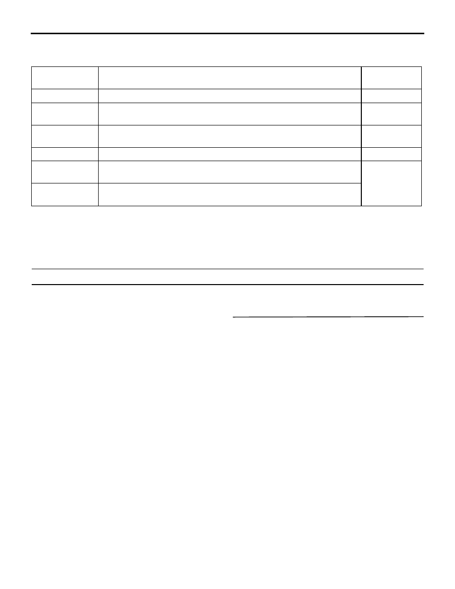
DIAGNOSIS CODE CHART
SMART WIRING SYSTEM (SWS) NOT USING SWS MONITOR
54B-17
DIAGNOSIS CODE CHART
M1549000700308
DIAGNOSTIC TROUBLE CODE PROCEDURES
Diagnosis code 11: Trouble related to the ETACS-ECU
DIAGNOSIS CODE SET CONDITIONS
The ETACS-ECU monitors the data, which the ECU
itself sends. If errors occur consecutively 15 times
(for 0.6 seconds), a diagnosis code will be set. Then,
if the data does not contain any errors consecutively
15 times (for 0.6 seconds), the ECU will stop sending
the diagnosis code.
POSSIBLE CAUSES
•
Malfunction of the ETACS-ECU
DIAGNOSTIC PROCEDURE
Check whether the diagnosis code is reset.
(1) Erase the diagnosis code.
(2) Again check that diagnosis code No.11 is set.
Q: Is diagnosis code No.11 set?
YES :
Replace the ETACS-ECU.
NO :
The trouble can be an intermittent
malfunction (Refer to GROUP 00
−
How to
Cope with Intermittent Malfunction
Code No.
Diagnosis Details
Reference
page
11
Trouble related to the ETACS-ECU
12
Trouble related to the column switch or improper connection with the
ETACS-ECU
13
Trouble related to the front-ECU or improper connection with the
ETACS-ECU
21
Short circuit in SWS communication line
31
Open circuit in signal line between the SRS-ECU and the ETACS-ECU
(impact detection signal)
32
Short circuit in signal line between the SRS-ECU and the ETACS-ECU
(impact detection signal)