Mitsubishi Outlander (2003+). Manual - part 409


  Index      Mitsubishi     Mitsubishi Outlander - service repair manual 2003 year


Search            


Content   ..  407  408  409  410   ..


Mitsubishi Outlander (2003+). Manual - part 409


IGNITION SWITCH

CHASSIS ELECTRICAL

54A-31

Registration of additional key(s) without using 
the MUT-III
If the MUT-III is not available, new key(s) can be 
registered by operating two keys which have been 
registered to the vehicle (A maximum of eight keys 
can be registered to one vehicle). Follow the 
procedure below to register new key(s) to the 
vehicle.
NOTE: The registered key is the key that allows you 
to start the engine.
1. Turn "ON" the ignition switch by using the first 

registered key (key A), and wait for five seconds.

2. Remove the first registered key (key A).
3. Insert the second registered ignition key (key B), 

and turn it to the ON position.

4. The immobilizer-ECU identifies the new key to 

accept or reject it, and operates the immobilizer 
indicator (See the table below). 

5. If a new ignition key is registered further, repeat 

steps 1 to 7 above.

A maximum of eight ignition keys can be registered 
to one vehicle (If you attempt to register the ninth 
key, the immobilizer-ECU rejects the key). If any of 
the following conditions are satisfied, the additional 
key registration mode will terminate:

The ignition switch has been on for more than 30 
seconds.

After the ignition key has been turned to the 
"LOCK" (OFF), the engine control relay is turned 
off.

The MUT-III has started communicating with 
vehicle systems.

6. After the registration mode has terminated, the 

additionally registered key(s) should allow you to 
start the engine.

TRANSPONDER LOCK CHECK <MUT-II>

M1543024100142

CAUTION

To prevent damage to MUT-II, always turn the 
ignition switch to "LOCK" (OFF) position before 
connecting or disconnecting MUT-II.
Follow the procedure below to judge if the ignition 
key can be overwritten (i.e. the ignition key is correct) 
or not.

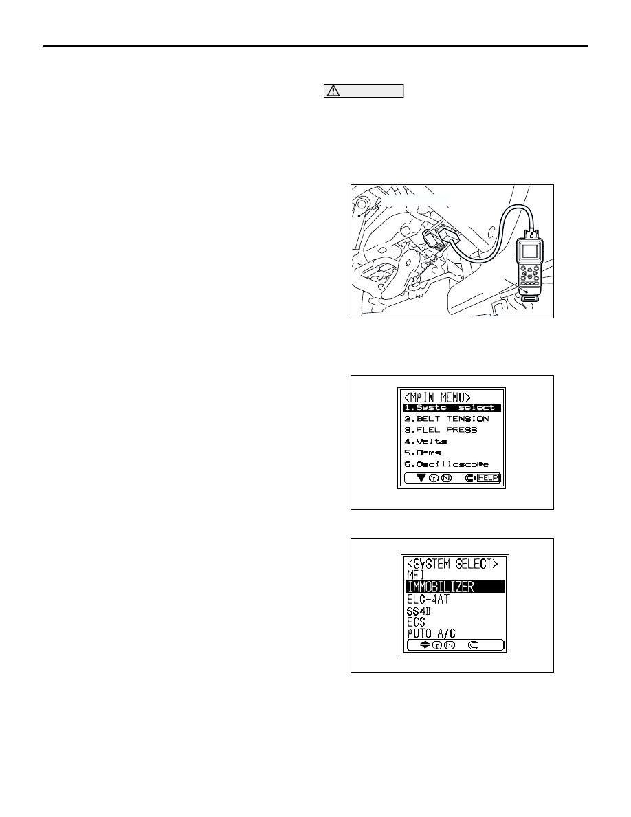
1. Connect MUT-II to the 16-pin diagnosis 

connector.

2. Turn the ignition switch to "ON" position.

3. At "System Select," press "YES."

4. Select "Immobilizer," press "YES".

AC300830

Steering shaft

MUT-II

AB

AC000522AD

AC000523AC

IGNITION SWITCH

CHASSIS ELECTRICAL

54A-32

5. Select "Data list" press "YES".

6. Confirm "TP LOCK CHECK."

TRANSPONDER LOCK CHECK <MUT-III>

CAUTION

To prevent damage to MUT-III, always turn the 
ignition switch to "LOCK" (OFF) position before 
connecting or disconnecting MUT-III.
Follow the procedure below to judge if the ignition 
key can be overwritten (i.e. the ignition key is correct) 
or not.

1. Connect the MUT-III to the diagnosis connector.
2. Turn the ignition switch to "ON" position.

3. Select "System select" from the start-up screen. 

4. Choose "IMMOBILIZER" from the "POWER 

TRAIN" tab.

TP Lock Check Ignition Key:

Judgment Of 
Ignition Key

UNLOCK

Can be 
overwritten

Correct

LOCK

Can not be 
overwritten

Incorrect

AC106459 AD

AC106460 AB

AC308915AB

MB991911

16-PIN

MB991827

MB991824 

System select

Special function

CAN bus diagnosis

Function Select Menu

Menu

AC209666

Maintenance

AD

MPI/GDI/DIESEL

ELC-A/T/CVT

IMMOBILIZER

SS4II

TCL/STARLTY CONTROL

AUTO CRUISE

CHASSIS

BODY

System Select Menu

POWER TRAIN

AC305175

IGNITION SWITCH

CHASSIS ELECTRICAL

54A-33

5. Select "Data List."

6. The multi-centre display shows whether the 

ignition key, which has been inserted in the 
switch, can be rewritten and how many ignition 
keys have ever been registered.

Check Chart For

 Problem Sy

Data List

Special 

Function

Self-diagnosis

Simulated Vehicle 

Speed Out

Resistor

Voltmeter

POWERTRAIN

IMMOBILIZER

IMMOBILIZER

AC305176

TP Lock Check Ignition Key:

Judgment Of 
Ignition Key

UNLOCK

Can be 
overwritten

Correct

LOCK

Can not be 
overwritten

Incorrect

AC209776

POWERTRAIN

IMMOBILIZER

Data List Reference Table

Info. No.

01

REGD.KEY

3

TP LOCK CHECK

UNLOCK

02

Name

Value

Graph

Data List

Data List

IGNITION SWITCH

CHASSIS ELECTRICAL

54A-34

IGNITION SWITCH

REMOVAL AND INSTALLATION

M1543002100489

WARNING

Before removal of the air bag module, refer to GROUP 52B, SRS Service Precautions 

P.52B-4

and Air Bag Module and Clock Spring 

P.52B-179

.

When removing and installing the steering wheel, do not let it bump against the air bag 
module.

AC309269

Section A – A

Claw

3

4

2

3

1

5

7

6

1.5 ± 0.5 N·m

2.5 ± 0.5 N·m

4

8

9

2.5 ± 0.5 N·m

NOTE
      
: Claw position

AB

A

A

Removal steps

1. Instrument lower panel (Refer to 

GROUP 52A, Instrument panel 

P.52A-2

 <LHD> or 

P.52A-8

 <RHD> )

2. Steering wheel (Refer to GROUP 37A, 

Steering wheel 

P.37A-16

)

3. Column cover upper
4. Column cover lower

Removal steps (Continued)


Content   ..  407  408  409  410   ..