Mitsubishi Outlander (2003+). Manual - part 373


  Index      Mitsubishi     Mitsubishi Outlander - service repair manual 2003 year


Search            


Content   ..  371  372  373  374   ..


Mitsubishi Outlander (2003+). Manual - part 373


TROUBLESHOOTING

SUPPLEMENTAL RESTRAINT SYSTEM (SRS)

52B-91

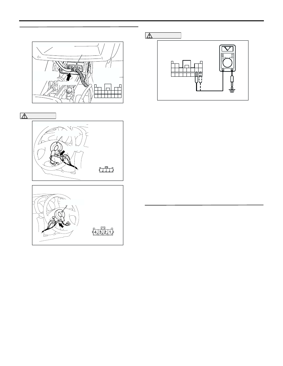
STEP 3. Measure the voltage at the SRS-ECU 
connector C-115.

(1) Disconnect SRS-ECU connector C-115.

DANGER

To prevents the air bag from deploying 
unintentionally, disconnect the clock spring 
connector C-307 to short the squib circuit.

(2) Disconnect the clock spring connector C-307.

(3) Turn the ignition switch to the "ON" position.

CAUTION

Do not insert a test probe into the terminal from 
its front side directly as the connector contact 
pressure may be weakened.
(4) Measure the voltage between C-115 harness 

side connector terminals 11, 12 and body earth.

OK: 0 V

Q: Is the check result normal?

YES : 

Erase the diagnosis code memory, and 

check the diagnosis code. If diagnosis code 
61 sets, replace the SRS-ECU (Refer to 

P.52B-178

). Then go to Step    .

NO : 

Repair the harness wires between 
SRS-ECU connector C-115 (terminal No.11 
and 12) and clock spring connector C-307 
(terminal No.3 and 4). Then go to Step 4.

STEP 4. Check whether the diagnosis code is 
reset.

Q: Is diagnosis code 61 set?

YES : 

Return to Step 1.

NO : 

The procedure is complete (If no 
malfunctions are found in all steps, an 
intermittent malfunction is suspected. Refer 
to GROUP 00 

 How to Use 

Troubleshooting/Inspection Service Points 

P.00-6

).

AC301661AC

Harness side
connector
(front view)

Connector: C-115

SRS-ECU

C-115 (Y)

Center lower
panel

1110 9

1

2

3

1413

12

4

5

6

16

8

15

7

17

18

19

20

AC301399

Connector: C-307<LHD>

Clock spring

C-307 (Y)

AJ

Harness side
connector
(front view)

3

4

2 1

AC308778

Connector: C-307 <RHD>

AF

C-307 (Y)

Clock spring

Harness side
connector
(front view)

13 14 15 16 17 18 19 20

5 6 7 8 9 10 11 12

1 2

3 4

AC301030AB

C-115 Harness side
connector (rear view)

TROUBLESHOOTING

SUPPLEMENTAL RESTRAINT SYSTEM (SRS)

52B-92

Code No.62: Driver's air bag module (squib) system (short-circuited to the earth)

OPERATION

The SRS-ECU judges how severe a collision is 
by detecting signals from the front impact sensors 
and the front air bag analog G-sensor. If the 
impact is over a predetermined level, the 
SRS-ECU outputs an ignition signal. At this time, 
if the front air bag safing G-sensor is on, the SRS 
air bag will inflate.

The ignition signal is input to the air bag module 
via the clock spring to inflate the air bag.

DIAGNOSIS CODE SET CONDITIONS
This diagnosis code is set if the driver's air bag squib 
wire(s) are short-circuited to the earth. However, if no 
diagnosis code resets, the SRS warning lamp will be 
switched off (diagnosis code will be retained).

PROBABLE CAUSES

Malfunction of the clock spring

Damaged harness wires and connectors

Short to the earth in the driver's air bag module 
(squib) harness

Malfunction of the SRS-ECU

CLOCK
SPRING

AIR BAG MODULE
(SQUIB)
(DRIVER'S SIDE)

CONNECTOR
LOCK
SWITCH

AIR BAG
DRIVE CIRCUIT

NOTE

CONNECTOR
COUPLED: ON
CONNECTOR
UNCOUPLED: OFF

SRS-ECU

MICROCOMPUTER

CONNECTOR
LOCK
SWITCH

CONNECTOR
LOCK
SWITCH

Wire colour code
B : Black     LG : Light green     G : Green     L : Blue     W : White     Y : Yellow     SB : Sky blue
BR : Brown     O : Orange     GR : Gray     R : Red     P : Pink     V : Violet   

AC301790

Driver's Air Bag Module (Squib) Circuit

AB

TROUBLESHOOTING

SUPPLEMENTAL RESTRAINT SYSTEM (SRS)

52B-93

DIAGNOSIS PROCEDURE

STEP 1. Check the driver's air bag module.
(1) Disconnect the negative battery terminal.

(2) By sliding the A section (in the figure) of air bag 

module connector C-306 in arrow direction, 
disconnect the connector.

(3) Connect special tool dummy resistor (MB991865) 

to special tool resistor harness (MB991866).

CAUTION

Do not insert a test probe into the terminal from 
its front side directly as the connector contact 
pressure may be weakened.
(4) Insert special tool (MB991866) into clock spring 

side air bag module connector C-306 by 
backprobing.

(5) Connect the negative battery terminal.

(6) Erase the diagnosis code memory, and check the 

diagnosis code.

Q:  Is diagnosis code 62 set?

YES : 

Go to Step 2.

NO : 

Replace the driver's air bag module (Refer 
to 

P.52B-179

). Then go to Step 4.

STEP 2. Check the clock spring.
(1) Disconnect the negative battery terminal.

(2) Disconnect the clock spring connector C-307.
(3) Connect special tool dummy resistor (MB991865) 

to special tool resistor harness (MB991866).

CAUTION

Do not insert a test probe into the terminal from 
its front side directly as the connector contact 
pressure may be weakened.
(4) Insert special tool (MB991866) into clock spring 

harness side connector C-307 (terminal No.3 and 
4) by backprobing.

(5) Connect the negative battery terminal.
(6) Erase the diagnosis code memory, and check the 

diagnosis code.

Q: Is diagnosis code 62 set?

YES : 

Go to Step 3.

NO : 

Replace the clock spring (Refer to 

P.52B-179

). Then go to Step 4.

AC300156AB

A

C-306 Air bag
module connector

Steering wheel

AC303006AC

MB991865
(Dummy resistor : 3

Ω)

MB991866
(Resistor harness)

C-306 Air bag 
module
connector

AC303587AC

1 2

4

3

MB991865 (Dummy
resistor : 3 

Ω)

MB991866
(Resistor harness)

C-307 Clock spring
connector

(Rear view)

TROUBLESHOOTING

SUPPLEMENTAL RESTRAINT SYSTEM (SRS)

52B-94

STEP 3. Check the driver’s air bag module circuit 
at the SRS-ECU connector C-115.

(1) Disconnect SRS-ECU connector C-115.

DANGER

To prevents the air bag from deploying 
unintentionally, disconnect the clock spring 
connector C-307 to short the squib circuit.

(2) Disconnect the clock spring connector C-307.

CAUTION

Do not insert a test probe into the terminal from 
its front side directly as the connector contact 
pressure may be weakened.
(3) Check for continuity between C-115 harness side 

connector terminals 11, 12 and body earth.

OK: Open circuit

Q: Is the check result normal.

YES : 

Erase the diagnosis code memory, and 

check the diagnosis code. If diagnosis code 
62 sets, replace the SRS-ECU (Refer to 

P.52B-178

). Then go to Step    .

NO : 

Repair the harness wires between 
SRS-ECU connector C-115 (terminal No.11 
and 12) and clock spring connector C-307 
(terminal No.3 and 4). Then go to Step 4.

STEP 4. Check whether the diagnosis code is 
reset.

Q: Is diagnosis code 62 set?

YES : 

Return to Step 1.

NO : 

The procedure is complete (If no 
malfunctions are found in all steps, an 
intermittent malfunction is suspected. Refer 
to GROUP 00 

 How to Use 

Troubleshooting/Inspection Service Points 

P.00-6

).

AC301661AC

Harness side
connector
(front view)

Connector: C-115

SRS-ECU

C-115 (Y)

Center lower
panel

1110 9

1

2

3

1413

12

4

5

6

16

8

15

7

17

18

19

20

AC301399

Connector: C-307<LHD>

Clock spring

C-307 (Y)

AJ

Harness side
connector
(front view)

3

4

2 1

AC308778

Connector: C-307 <RHD>

AF

C-307 (Y)

Clock spring

Harness side
connector
(front view)

13 14 15 16 17 18 19 20

5 6 7 8 9 10 11 12

1 2

3 4

AC301033AB

C-115 Harness side connector (rear view)


Content   ..  371  372  373  374   ..