Mitsubishi Outlander (2003+). Manual - part 340


  Index      Mitsubishi     Mitsubishi Outlander - service repair manual 2003 year


Search            


Content   ..  338  339  340  341   ..


Mitsubishi Outlander (2003+). Manual - part 340


DOOR MIRROR

EXTERIOR

51-59

>>B<< DOOR MIRROR ASSEMBLY 
INSTALLATION

CAUTION

When assembling the door mirror, check to see 
that the thumb of the door mirror is inserted in 
the cut-out of the front door runchannel.
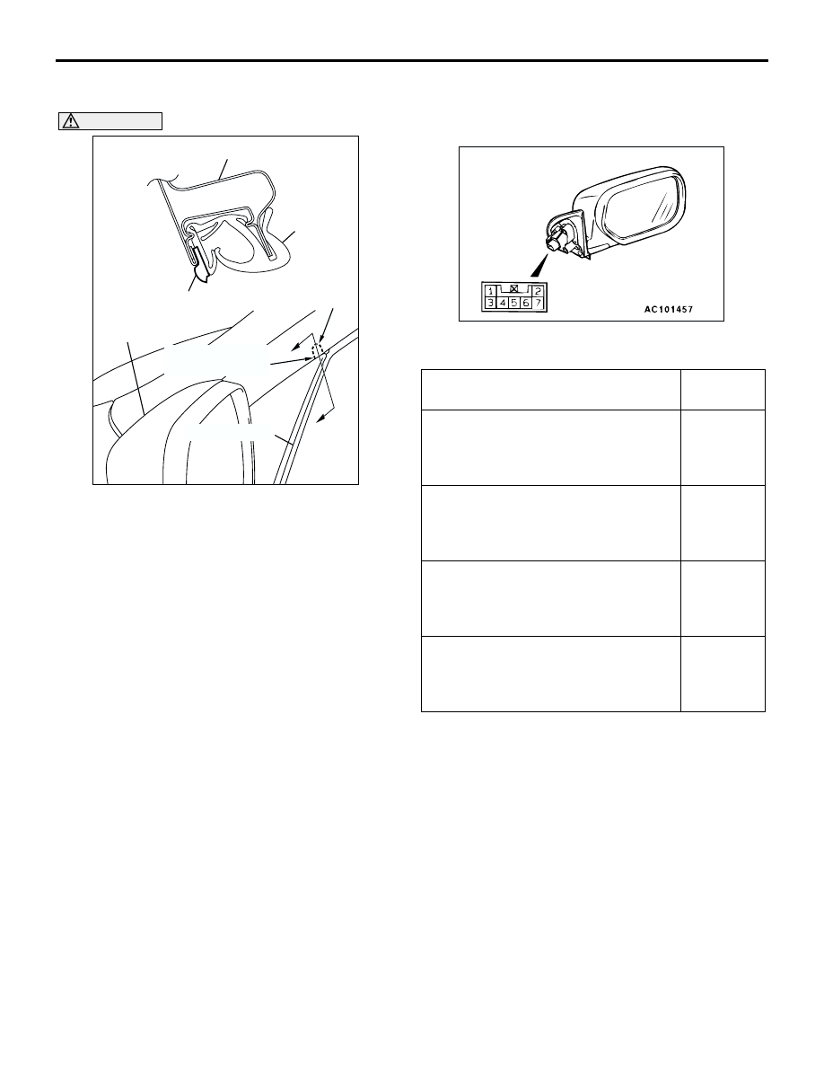
INSPECTION

M1511006500350

ELECTRIC REMOTE CONTROL MIRROR 
OPERATION CHECK

Check that the mirror moves as described in the 
table when each terminal is connected to the battery.

AC103753

Section A – A

A

A

Notch

Door mirror
claw position

Door panel

Runchannel

Door mirror

Door mirror
claw position

Runchannel

AC

Battery connection

Direction 
operation

Connect terminal 5 to the negative 
battery terminal.

Connect terminal 7 to the positive 
battery terminal.

Up

Connect terminal 5 to the positive 
battery terminal.

Connect terminal 7 to the negative 
battery terminal.

Down

Connect terminal 5 to the negative 
battery terminal.

Connect terminal 6 to the positive 
battery terminal.

Right

Connect terminal 5 to the positive 
battery terminal.

Connect terminal 6 to the negative 
battery terminal.

Left

DOOR MIRROR

EXTERIOR

51-60

DOOR MIRROR CONTROL SWITCH CONTINUITY 
CHECK

HEATED DOOR MIRROR CHECK

CAUTION

When relocating the car between locations with 
extremely different temperatures (warm and 
cold), leave the car in the location for a while to 
adapt to the temperature prior to checking it.

Check to see that the resistance shown in the graph 
is almost satisfied when measuring the resistance of 
terminal 1 and 2 of the door mirror connectors under 
2 or more different temperature conditions.

Switch position

Tester 
connection

Specified 
condition

OFF

 2, 9 

 3, 9 

 6, 

 10, 9 

 11, 1 


2, 1 

 3, 1 

 6, 1 


10, 1 

 11

Open circuit

Left side OFF

 6, 9 

 10, 9 


11, 1 

 6, 1 

 10, 

 11

Open circuit

Up

 6, 9 

 11

Less than 2 
ohms

Down

 11, 6 

 9

Right

 6, 9 

 10

Left

 10, 6 

 9

Right 
side

OFF

 2, 9 

 3, 9 

 6, 

 2, 1 

 3, 1 

 6

Open circuit

Up

 6, 3 

 9

Less than 2 
ohms

Down

 3, 6 

 9

Right

 6, 2 

 9

Left

 2, 6 

 9

AC005970

2

1

4

3

5

10

9

8

7

6

11

AC201611

Resistance

Temperature (˚C)

-10

0

10

20

30

40

(

)

0

2

4

6

8

10

AC

12

Upper limit value

Lower limit value

52A-1

GROUP 52A

INTERIOR

CONTENTS

SPECIAL TOOL . . . . . . . . . . . . . . . . .

52A-2

INSTRUMENT PANEL ASSEMBLY*.

52A-2

REMOVAL AND INSTALLATION 

<L.H. DRIVE VEHICLES>. . . . . . . . . . . . . . 

52A-2

DISASSEMBLY AND REASSEMBLY. . . . . 

52A-7

REMOVAL AND INSTALLATION 

<R.H. DRIVE VEHICLES>  . . . . . . . . . . . . . 

52A-8

DISASSEMBLY AND REASSEMBLY. . . . . 

52A-13

FLOOR CONSOLE ASSEMBLY . . . .

52A-14

REMOVAL AND INSTALLATION . . . . . . . . 

52A-14

DISASSEMBLY AND REASSEMBLY. . . . . 

52A-16

TRIMS. . . . . . . . . . . . . . . . . . . . . . . . .

52A-18

REMOVAL AND INSTALLATION . . . . . . . . 

52A-18

DOOR TRIM . . . . . . . . . . . . . . . . . . . .

52A-21

REMOVAL AND INSTALLATION . . . . . . . . 

52A-21

DISASSEMBLY AND REASSEMBLY. . . . . 

52A-24

TAILGATE TRIM  . . . . . . . . . . . . . . . .

52A-25

REMOVAL AND INSTALLATION . . . . . . . . 

52A-25

HEADLINING  . . . . . . . . . . . . . . . . . . .

52A-27

REMOVAL AND INSTALLATION . . . . . . . . 

52A-27

INSIDE REAR VIEW MIRROR . . . . . .

52A-28

FRONT SEAT ASSEMBLY* . . . . . . . .

52A-29

REMOVAL AND INSTALLATION . . . . . . . . 

52A-29

INSPECTION. . . . . . . . . . . . . . . . . . . . . . . . 

52A-31

DISASSEMBLY AND REASSEMBLY . . . . . 

52A-33

REAR SEAT ASSEMBLY. . . . . . . . . .

52A-36

REMOVAL AND INSTALLATION . . . . . . . . 

52A-36

DISASSEMBLY AND REASSEMBLY . . . . . 

52A-37

FRONT SEAT BELT* . . . . . . . . . . . . .

52A-39

REMOVAL AND INSTALLATION . . . . . . . . 

52A-39

REAR SEAT BELT . . . . . . . . . . . . . . .

52A-40

REMOVAL AND INSTALLATION . . . . . . . . 

52A-40

WANINGS REGARDING SERVICING OF SUPPLEMENTAL RESTRAINT SYSTEM (SRS) EQUIPPED VEHICLES

WARNING

Improper service or maintenance of any component of the SRS, or any SRS-related component, can lead to 

personal injury or death to service personnel (from inadvertent firing of the air bag) or to the driver and 

paassenger (from rendering the SRS inoperative).

Service or maintenance of any SRS component or SRS-related component must be performed only at an 

authorized MITSUBISHI dealer.

MITSUBISHI dealer personnel must thoroughly review this manual, and especially its GROUP 52B - Supplemental 

Restraint System (SRS) before beginning any service or maintenance of any component of the SRS or any 

SRS-related component.

NOTE

The SRS includes the following components: SRS air bag control unit, SRS warning light, front impact sensors, air bag module,

clock spring, and interconnecting wiring. Other SRS-related components (that may have to be removed/installed in connection

with SRS service or maintenance) are indicated in the table of contents by an asterisk (*).

SPECIAL TOOL

INTERIOR

52A-2

SPECIAL TOOL

M1521000600264

INSTRUMENT PANEL ASSEMBLY

REMOVAL AND INSTALLATION 
<L.H. DRIVE VEHICLES>

M1521001700491

WARNING

For removal and installation of the passenger's side air bag module, always observe the 
service procedures described in GROUP 52B, Air Bag Module and Clock Spring 

P.52B-179

.

The following bolts and screws are used for installing the instrument panel. Bolts and screws are indicated as 
marks shown in the illustration in the sections of "Removal and Installation" and "Disassembly and 
Assembly."

Tool

Tool number

Name

Use

MB990784

Ornament remover

Removal of switch, trim, etc.

MB990784

Name

Symbol

Size (D 

×

 L) mm

Colour

Shape

Tapping screw

a

×

 12

-

b

×

 16

-

c

×

 16

Black

d

×

 12

-

e

×

 20

-

Washer assembly bolt

f

×

 16

-

g

×

 16

-

h

×

 16 (Earth)

-

i

×

 20 

-

j

10 

×

 60

-

AC104450

AC104436

AC104417

AC200304


Content   ..  338  339  340  341   ..