Mitsubishi Outlander (2003+). Manual - part 302


  Index      Mitsubishi     Mitsubishi Outlander - service repair manual 2003 year


Search            


Content   ..  300  301  302  303   ..


Mitsubishi Outlander (2003+). Manual - part 302


POWER STEERING GEAR BOX AND LINKAGE

POWER STEERING

37A-31

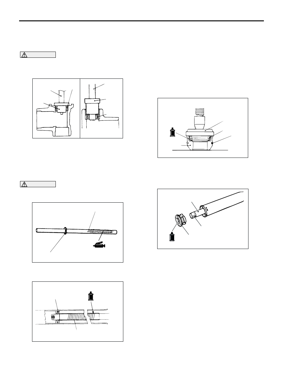
>>B<< NEEDLE BEARING/LOWER BEARING 
INSTALLATION
1. Apply ATF DEXRON III or DEXRON II to housing, 

bearing and oil seal press fitting surface.

CAUTION

Press-fit straight. The valve housing is 
aluminium, and may become deformed if 
press-fit on an angle.

2. Press fit needle bearing with the following special 

tools.

MB990938: Bar (Snap-in type)

MB991202: Oil Seal and Bearing Installer

>>C<< RACK ASSEMBLY INSTALLATION

CAUTION

Do not close the vent hole in the rack with 
grease.

1. Apply a coating of repair kit grease to the rack 

teeth face.

2. Cover rack serrations with special tool rack 

installer (MB991213).

3. Apply ATF DEXRON III or DEXRON II to special 

tool, and to the outer surface of the seal ring and 
the O-ring.

4. Align the centre of the oil seal with the rack to 

prevent the retainer spring from slipping. Slowly 
insert the rack from power cylinder side.

>>D<< OIL SEAL/RACK BUSHING 
INSTALLATION

1. Apply ATF DEXRON III or DEXRON II to the outer 

surface of the oil seal. Using the special tool 
installer adapter (MB990927), press in the oil seal 
until it is flush with the bushing end face.

2. Apply ATF DEXRON III or DEXRON II to the oil 

seal inner surface and the O-ring.

3. Wrap the rack end with plastic tape, and push the 

rack bushing onto the rack.

ACX01153

Needle bearing

MB990938

MB991202

MB991202

Lower 
bearing

AE

MB990938

ACX01154 AB

Seal ring and O-ring

Vent hole

ACX01155

MB991213

AB

Oil seal

ACX01156 AE

Oil seal

O-ring

MB990927

Rack 
bushing

AC100261AB

Rack

Vinyl tape

Rack bushing

POWER STEERING GEAR BOX AND LINKAGE

POWER STEERING

37A-32

>>E<< CIRCLIP INSTALLATION

CAUTION

Insert the circlip to the rack stopper hole while 
turning the rack stopper clockwise.

Insert the circlip to the rack stopper hole through 
cylinder hole. Turn the rack stopper clockwise and 
insert the circlip firmly.

>>F<< UPPER OIL SEAL/UPPER BEARING 
INSTALLATION

Apply a coating of ATF DEXRON III or DEXRON II to 
the outside of the upper oil seal/upper bearing. Using 
the following special tools, press the upper oil 
seal/upper bearing into the valve housing.

MB990938: Bar (Snap-in type)

MB991203: Oil Seal and Bearing Installer

>>G<< SEAL RING INSTALLATION

Because the seal rings expand after installation, 
tighten after installing by using special tool seal ring 
installer (MB991317) to compress the rings, or press 
down by hand.

>>H<< LOWER OIL SEAL INSTALLATION

CAUTION

To eliminate a seal malfunction at the valve 
housing alignment surface, the upper surface of 
the oil seal should project outward 
approximately 1 mm from the housing edge 
surface.
Using special tool torque tube bearing installer 
(MB990941), press the oil seal into the valve 
housing.

>>I<< END PLUG INSTALLATION

1. Apply specified sealant to the threaded part of the 

end plug.

Specified sealant:
3M ATD Part No.8661, 8663 or equivalent

2. Secure the threaded portion of the end plug at two 

places by using a punch.

ACX01158

Circlip

Slot

AB

Circlip

Slot

ACX01159AC

MB990938

MB991203

Oil seal

MB991203

Bearing

MB990938

ACX01160 AB

MB991317

ACX01161

Housing

AC

Oil
seal

Approximately
1 mm

MB990941

ACX01162 AB

End plug

End plug

POWER STEERING GEAR BOX AND LINKAGE

POWER STEERING

37A-33

>>J<< RACK SUPPORT COVER/JAM NUT 
INSTALLATION
1. Position the rack at its centre.
2. Apply specified sealant to the threaded part of the 

rack support cover.

Specified sealant:
3M ATD Part No.8661, 8663 or equivalent

3. Use special tool rack support cover wrench 

(MB991621) to tighten the rack support cover to 
23 

±

 2 N

m.

4. Turn the rack support cover 30

°

 counterclockwise.

5. Use the special tool to hold the rack support 

cover, and then tighten the jam nut to 59 

±

 10 

N

m.

>>K<< TOTAL PINION TORQUE ADJUSTMENT

CAUTION

Be sure there is no ratcheting or catching 
when operating the rack towards the shaft.

Measure the total pinion torque through the 
whole stroke of the rack.

1. Using special tool preload socket (MB991006), 

rotate the pinion shaft at the rate of one rotation in 
four to six seconds to check the total pinion torque 
and the change in torque.

Standard value:
Total pinion torque: 0.7 

 1.6 N

m

[Change in torque: 0.4 N

m or less]

CAUTION

When adjusting, set at the highest value of the 
standard value range.

NOTE: If the total pinion toque cannot be adjusted 
to the standard value within the specified return 
angle, check the rack support cover components 
and replace any parts if necessary.

2. If the total pinion torque or the change in torque is 

outside the standard value, move the rack support 
cover 0 

 30

°

, and adjust the pinion torque again.

>>L<< TAB WASHER/TIE ROD INSTALLATION

After installing the tie rod to the rack, fold tab washer 
end (two locations) to tie rod notch.

>>M<< BELLOWS BAND INSTALLATION

1. Turn the adjusting bolt of special tool boot band 

crimping tool (MB991561) to adjust the opening 
dimension (W) to the standard value.
NOTE: The dimension (W) is adjusted by 
approximately 0.7 mm per one turn.
NOTE: Do not turn the adjusting bolt more than 
one turn.

Standard value (W): 2.9 mm
<When more than 2.9 mm>: Screw in the 
adjusting bolt.
<When less than 2.9 mm>: Loosen the 
adjusting bolt.

AC100273

MB991621

AC

AC100274AB

MB991006

ACX01163 AB

ACX01164 AB

W

MB991561

Adjusting bolt

Stopper

POWER STEERING GEAR BOX AND LINKAGE

POWER STEERING

37A-34

CAUTION

Hold the rack housing, and use special tool to 
crimp the bellows band securely.

Crimp the bellows band until special tool 
touches the stopper.

2. Use special tool boot band crimping tool 

(MB991561) to crimp the bellows band.

3. Check that crimped width (A) is within the 

standard value.

Standard value (A): 2.4 

 2.8 mm

<When more than 2.8 mm>: Readjust the 
dimension (W) of step (1) to the value 
calculated by the following equation, and 
repeat step (2).
 W = 5.5 mm 

 A [Example: if (A) is 2.9 mm, 

(W) is 2.6 mm.]

<When less than 2.4 mm>: Remove the 
bellows band, readjust the dimension (W) of 
step (1) to the value calculated by the 
following equation, and use a new bellows 
band to repeat steps (2) to (3).
W = 5.5 mm 

 A [Example: if (A) is 2.3 mm, 

(W) is 3.2 mm.]

>>N<< TIE ROD END/JAM NUT INSTALLATION

Screw in the tie rod end to achieve the right and left 
length as illustrated. Lock with the jam nut.
NOTE: The jam nuts must be tightened securely only 
after the steering gear is installed to the vehicle and 
toe-in is adjusted.

>>O<< GEAR MOUNTING RUBBER 
INSTALLATION

Install the gear mounting rubber to the rack housing 
so that the distance is as shown in the illustration.

ACX01165 AB

MB991561

ACX01166 AB

A

AC001011 AH

Jam nut

Edge of bellows
assembly groove

186 mm

AC100275AB

220 mm


Content   ..  300  301  302  303   ..