Mitsubishi Outlander (2003+). Manual - part 299


  Index      Mitsubishi     Mitsubishi Outlander - service repair manual 2003 year


Search            


Content   ..  297  298  299  300   ..


Mitsubishi Outlander (2003+). Manual - part 299


STEERING SHAFT

POWER STEERING

37A-19

REMOVAL SERVICE POINT

<<A>> STEERING COLUMN SHAFT ASSEMBLY 
REMOVAL

CAUTION

The tilt lever should be held in the lock position 
until the steering column shaft is installed to the 
vehicle. If the steering column is removed with 
the tilt lever released, or the tilt lever is released 
after the steering column shaft was removed 
from the vehicle, the steering column can not be 
reinstalled correctly. If the steering column is 
installed incorrectly, the collision energy 
absorbing mechanism may be damaged.
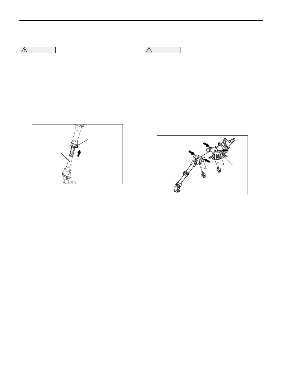
1. Ensure that the tilt lever is in the lock position, and 

remove the steering column mounting bolts.

2. Pinch the steering column shaft clip with pliers, 

and pull up the shaft towards the direction shown 
to disengage the steering column shaft assembly.

INSTALLATION SERVICE POINT

>>A<< STEERING COLUMN SHAFT ASSEMBLY 
INSTALLATION

CAUTION

When reusing the steering column, do not 
release the tilt lever until the steering column 
shaft has been installed.

When the steering column is replaced, do not 
release the tilt lever until it has been installed. 
Do not remove the tilt lever fixing band until 
the installation has completed.

When installing the steering column, do not 
leave it fixed temporarily at only one point 
and make sure the column shaft is not shaken 
strongly. If you fail to do, the collision 
absorbing mechanism at the column shaft 
mounting location may be damaged.

Ensure that the tilt lever is in the lock position, and 
install the steering column. Tighten the four bolts in 
the order shown by hand, and then tighten them to 
the specified torque in the order shown.

Tightening torque: 12 

±

 2 N

m

AC210969AD

Clip

Steering column 
shaft

AC209383AD

1

4

3

2

Tilt lever

STEERING SHAFT

POWER STEERING

37A-20

 DISASSEMBLY AND REASSEMBLY

M1372011700128

DISASSEMBLY SERVICE POINT

<<A>> SPECIAL BOLT REMOVAL

1. Drill in the special bolt a hole deep enough for the 

tap to stand.

2. Remove the special bolt with a left-hand tap.

REASSEMBLY SERVICE POINT

>>A<< STEERING LOCK CYLINDER 
ASSEMBLY/STEERING LOCK 
BRACKET/SPECIAL BOLT INSTALLATION

CAUTION

The steering lock bracket and bolts must be 
replaced with new ones when the steering lock is 
installed.
1. When installing the steering lock cylinder 

assembly and steering lock bracket to the column 
tube, temporarily install the steering lock in 
alignment with the column boss.

2. After checking that the lock works properly, 

tighten the special bolts until the head twists off.

AC210967AD

3

2

1

4

Disassembly steps

<<A>> >>A<<

1.

Special bolt

>>A<<

2.

Steering lock bracket

>>A<<

3.

Steering lock cylinder assembly

4.

Steering column shaft assembly

ACX01138 AB

Steering lock 
bracket

Reverse screw tap

Special bolt

Steering lock 
cylinder

ACX01139 AB

POWER STEERING GEAR BOX AND LINKAGE

POWER STEERING

37A-21

POWER STEERING GEAR BOX AND LINKAGE

REMOVAL AND INSTALLATION

M1372010900282

WARNING

Before removing the steering gear, refer to GROUP 52B, Service Precautions (

P.52B-4

) and 

Air Bag Module and Clock Spring (

P.52B-179

). Centre the front wheels. Failure to do so may 

damage the SRS clock spring and render the SRS system inoperative, risking serious injury.

Pre-removal Operation

Power Steering Fluid Draining (Refer to 

P.37A-11

).

Front Exhaust Pipe Removal (Refer to GROUP 15, 

Exhaust Pipe and Main Muffler 

P.15-13

).

Centermember Removal (Refer to GROUP 32, Engine 

Roll Stopper and Centermember 

P.32-10

 <2000>, 

P.32-12

 <2400>).

Steering Wheel and Air Bag Module Assembly Removal 
(Refer to 

P.37A-16

).

Clock Spring Removal (Refer to GROUP 52B, Air Bag 
Module and Clock Spring 

P.52B-179

).

Stabilizer Link Assembly and Lower Arm Assembly 
Removal (Refer to GROUP 33A, Lower Arm 

P.33-11

).

Post-installation Operation

Stabilizer Link Assembly and Lower Arm Assembly 
Installation (Refer to GROUP 33A, Lower Arm 

P.33-11

).

Centermember Installation (Refer to GROUP 32, Engine 
Roll Stopper and Centermember 

P.32-10

 <2000>, 

P.32-12

 <2400>).

Front Exhaust Pipe Installation (Refer to GROUP 15, 

Exhaust Pipe and Main Muffle

P.15-13

).

Clock Spring Installation (Refer to GROUP 52B, Air Bag 

Module and Clock Spring 

P.52B-179

).

Steering Wheel and Air Bag Module Assembly Installation 

(Refer to 

P.37A-16

).

Check the dust cover for cracks or damage by pushing it 

with your finger.

Power Steering Fluid Supplying (Refer to 

P.37A-11

).

Power Steering Fluid Line Bleeding (Refer to 

P.37A-12

).

Checking Steering Wheel Position with Wheels Straight 

Ahead.

Front Wheel Alignment Adjustment (Refer to GROUP 

33A, On-vehicle Service 

 Front Wheel Alignment Check 

and Adjustment 

P.33-6

).

POWER STEERING GEAR BOX AND LINKAGE

POWER STEERING

37A-22

<L.H. drive vehicles>

AC300496AB

15 ± 3 N·m

70 ± 10 N·m

6

3

7

4

5

8

2

1

12 ± 2 N·m

18 ± 2 N·m

25 ± 5 N·m

57 ± 7 N·m

9

10

18 ± 2 N·m

11 

4

70 ± 10 N·m

12

13

49 ± 10 N·m

167 ± 9 N·m

7

12 ± 2 N·m

Removal steps

1. Shaft cover
2. Steering column shaft assembly and 

steering gear connecting bolt

<<A>>

3. Tie rod end and knuckle connection 

Rear roll stopper connecting bolt 
(Refer to GROUP 32, Engine Roll 
Stopper and Centermember 

P.32-10


<2000>

P.32-12

 <2400>.)

4. Return hose connection
5. Return tube
6. O-ring
7. Pressure hose connection

8. Gasket

<<B>>

Crossmember assembly

Rear roll stopper (Refer to GROUP 32, 
Engine Roll Stopper and 
Centermember 

P.32-10

 <2000>, 

P.32-12

 <2400>.)

>>A<<

9. Joint cover grommet
10. Steering extension
11. Return tube
12. Crossmember
13. Steering gear

Removal steps (Continued)


Content   ..  297  298  299  300   ..