Mitsubishi Outlander (2003+). Manual - part 297


  Index      Mitsubishi     Mitsubishi Outlander - service repair manual 2003 year


Search            


Content   ..  295  296  297  298   ..


Mitsubishi Outlander (2003+). Manual - part 297


ON-VEHICLE SERVICE

POWER STEERING

37A-11

STEERING WHEEL RETURN TO CENTRE 
CHECK

M1372001800384

Conduct a road test:
1. Make both gradual and sudden turns and check 

the steering wheel return. 

2. At a vehicle speed of approximately 35 km/h, turn 

the steering wheel 90

°

, hold a few seconds, then 

release. If the steering wheel then returns 70

°

 or 

more, the return can be judged satisfactory.
NOTE: There will be a momentary feeling or 
"heaviness" when the wheel is turned quickly, but 
this is not abnormal (Oil pump discharge amount 
is especially apt to be insufficient during idling). 

DRIVE BELT TENSION CHECK

M1372001900336

Refer to GROUP 11A, On-vehicle Service 

 Drive 

Belt Tension Check <2000> 

P.11A-8

.

Refer to GROUP 11C, On-vehicle Service 

 Drive 

Belt Tension Check <2400> 

P.11C-8

.

FLUID LEVEL CHECK

M1372002000358

1. Park the vehicle on a flat, level surface.
2. Start the engine, and then turn the steering wheel 

several times to raise the temperature of the fluid 
to approximately 50 

 60

°

C.

3. With the engine running, turn the wheel all the 

way to the left and right several times.

4. Check the fluid in the oil reservoir for foaming or 

milkiness. Check the difference of the fluid level 
when the engine is stopped, and while it is 
running. If the change of the fluid level is 5 mm or 
more, air bleeding should be done.
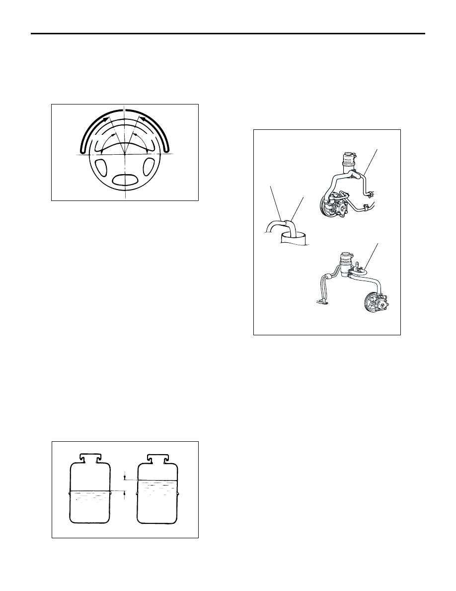
FLUID REPLACEMENT

M1372002100418

1. Raise and support the front wheels.

2. Disconnect the return hose connection, and then 

connect a vinyl hose to the return hose, and drain 
the fluid into a container.

3. Disconnect the ignition coil connectors (Refer to 

GROUP 16, Ignition Coil 

P.16-40

 <2000>, 

P.16-41

 <2400>).

4. While operating the starter motor intermittently, 

turn the steering wheel all the way to the left and 
right several times to drain all of the fluid.

5. Connect the return hose securely, and then 

secure with the clip.

6. Fill the oil reservoir with specified fluid up to the 

lower position of the filler, and then bleed the air.

Specified fluid: ATF DEXRON III or DEXRON 
II

ACX01130AB

70˚

70˚

ACX01131

While engine running

While engine stopped

AC

Fluid level change: Within 5 mm

AC309079AC

Return hose

Vinyl hose

Return hose

<2000>

<2400>

Return hose

ON-VEHICLE SERVICE

POWER STEERING

37A-12

POWER STEERING SYSTEM AIR 
BLEEDING

M1372002200404

Perform air bleeding procedure as necessary after 
replacing the steering gear or the steering fluid lines.
1. Raise and support the front wheels.
2. Disconnect the ignition coil connectors (Refer to 

GROUP 16, Ignition Coil 

P.16-40

 <2000>, 

P.16-41

 <2400>).

CAUTION

Perform air bleeding only while cranking the 
engine. If air bleeding is performed while the 
engine is running, air could enter the fluid. 
During air bleeding, refill the steering fluid 
supply so that the level never falls below the 
"MIN" mark on the oil reservoir.
3. Turn the steering wheel all the way to the left and 

right five or six times while using the starter motor 
to crank the engine intermittently several times 
(for 15 to 20 seconds).

4. Connect the ignition coil connectors (Refer to 

GROUP 16, Ignition Coil 

P.16-40

 <2000>, 

P.16-41

 <2400>).

5. Start the engine (idling).
6. Turn the steering wheel to the left and right until 

there are no air bubbles in the oil reservoir.

7. Confirm that the fluid is not milky, and that the 

level is between "MAX" and "MIN" marks.

8. Confirm that there is very little change in the fluid 

level when the steering wheel is turned left and 
right.

CAUTION

If the fluid level rises suddenly after the engine is 
stopped, the air has not been completely bled. If 
air bleeding is not complete, there will be 
abnormal noises from the pump and the 
flow-control valve, and this condition could 
cause reduce the life of the power steering 
components.

9. Confirm that the change in the fluid level is no 

more than 5 mm when the engine is stopped and 
when it is running.

10.If the change of the fluid level is 5 mm or more, 

the air has not been completely bled from the 
system. The air bleeding procedure must be 
repeated.

ACX01131

While engine running

While engine stopped

AC

Fluid level change: Within 5 mm

ON-VEHICLE SERVICE

POWER STEERING

37A-13

OIL PUMP PRESSURE TEST

M1372002300382

1. Disconnect the pressure hose from the oil pump, 

and then connect the following special tools.

MB990662: Power Steering Oil Pressure Gauge

MB991548: Power Steering Oil Pressure Gauge 
Adapter (Pump Side)

MB991549: Power Steering Oil Pressure Gauge 
Adapter (Hose Side)

2. Bleed air, then turn the steering wheel several 

times while the vehicle is not moving so that the 
temperature of the fluid rises to approximately 50 

 60

°

C.

3. Start the engine and idle it at 750 

±

 100 r/min.

CAUTION

The pressure gauge shut-off valve must not 
remain closed for more than 10 seconds.
4. Fully close the shut-off valve of the pressure 

gauge and measure the oil pump relief pressure 
to confirm that it is within the standard value 
range. Open it again immediately after checking 
the pressure.

Standard value: 8.8 

 9.5 MPa

5. If it is not within the standard value, replace the oil 

pump.

6. Check whether or not the hydraulic pressure is 

the standard value when no-load conditions are 
created by fully opening the shut-off valve of the 
pressure gauge.

Standard value: 0.8 

 1.0 MPa

7. If it is not within the standard value, the probable 

cause is a malfunction of the oil line or steering 
gear, so check these parts and repair as 
necessary.

8. Turn the steering wheel all the way to the left or 

right; then check whether or not the retention 
hydraulic pressure is the standard value.

Standard value: 8.8 

 9.5 MPa

9. If not the standard value, overhaul the steering 

gear. Remeasure fluid pressure.

10. Remove the special tools, and then tighten the 

pressure hose to the specified torque.

Tightening torque: 57 

±

 7 N

m

11. Bleed the system (Refer to 

P.37A-12

).

ACX01133

Temperature
gauge

Oil reservoir

Adapter
(MB991548)

Oil 
pump

Adapter
(MB991549)

AB

Shut-off valve
(fully closed)

Pressure 
gauge
(MB990662)

ON-VEHICLE SERVICE

POWER STEERING

37A-14

POWER STEERING PRESSURE SWITCH 
CHECK

M1372007200391

1. Disconnect the pressure hose from the oil pump, 

and then connect the following special tools.

MB990662: Power Steering Oil Pressure Gauge

MB991548: Power Steering Oil Pressure Gauge 
Adapter (Pump Side)

MB991549: Power Steering Oil Pressure Gauge 
Adapter (Hose Side)

2. Bleed air, and then turn the steering wheel several 

times while the vehicle is not moving so that the 
temperature of the fluid rises to approximately 50 

 60

°

C.

3. The engine should be idling.
4. Disconnect the connector for the oil pressure 

switch, and place an ohmmeter at the switch.

5. Gradually close the shut-off valve of the pressure 

gauge and increase the hydraulic pressure, then 
check whether or not the hydraulic pressure that 
activates the switch is the standard value.

Standard value: 1.5 

 2.0 MPa

6. Gradually open the shut-off valve and reduce the 

hydraulic pressure; then check whether or not the 
hydraulic pressure that deactivates the switch is 
the standard value.

Standard value: 0.7 

 2.0 MPa

7. Remove the special tools, and then tighten the 

pressure hose to the specified torque.

Tightening torque: 57 

±

 7 N

m

8. Bleed the system (Refer to 

P.37A-12

).

TIE ROD END BALL JOINT DUST COVER 
CHECK

M1372008600336

1. Press the dust cover with your finger to check 

whether the dust cover is cracked or damaged.

2. If the dust cover is cracked or damaged, replace 

the tie rod end.
NOTE: If the dust cover is cracked or damaged, 
the ball joint could be damaged.

ACX01134 AB

Temperature 
gauge

Adapter
(MB991548)

Oil reservoir

Oil
pump

Adapter
(MB991549)

Shut-off valve

Pressure gauge
(MB990662)


Content   ..  295  296  297  298   ..