Mitsubishi Outlander (2003+). Manual - part 296
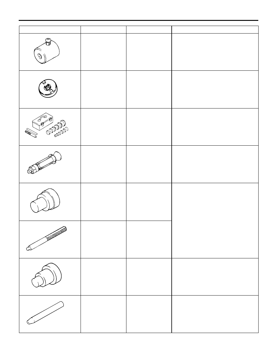
SPECIAL TOOLS
POWER STEERING
37A-7
MB990228 or
MB991006
Preload socket
Steering gear total pinion torque
check and adjustment
MB991621
Rack support cover
wrench
•
Rack support adjustment
•
Rack support cover removal
MB990925
Bearing and oil
seal installer set
•
Oil seal and bearing installation
•
MB990927, MB990938, MB990939
(For details, refer to GROUP 26,
Special Tools
).
MB991120
Needle bearing
puller
Needle roller bearing removal
MB991199
Oil seal and
bearing installer
Oil seal installation
MB991197
Bar (long type)
MB991202
Oil seal and
bearing installer
•
Needle bearing installation
•
Lower bearing installation
MB991213
Rack installer
Rack installation
Tool
Number
Name
Use
MB991006
MB991621
MB990925
MB991120
MB991199
AB
MB991197
MB991202
MB991212