Mitsubishi Outlander (2003+). Manual - part 210


  Index      Mitsubishi     Mitsubishi Outlander - service repair manual 2003 year


Search            


Content   ..  208  209  210  211   ..


Mitsubishi Outlander (2003+). Manual - part 210


TROUBLESHOOTING <A/T>

AUTOMATIC TRANSMISSION (FF)

23A-135

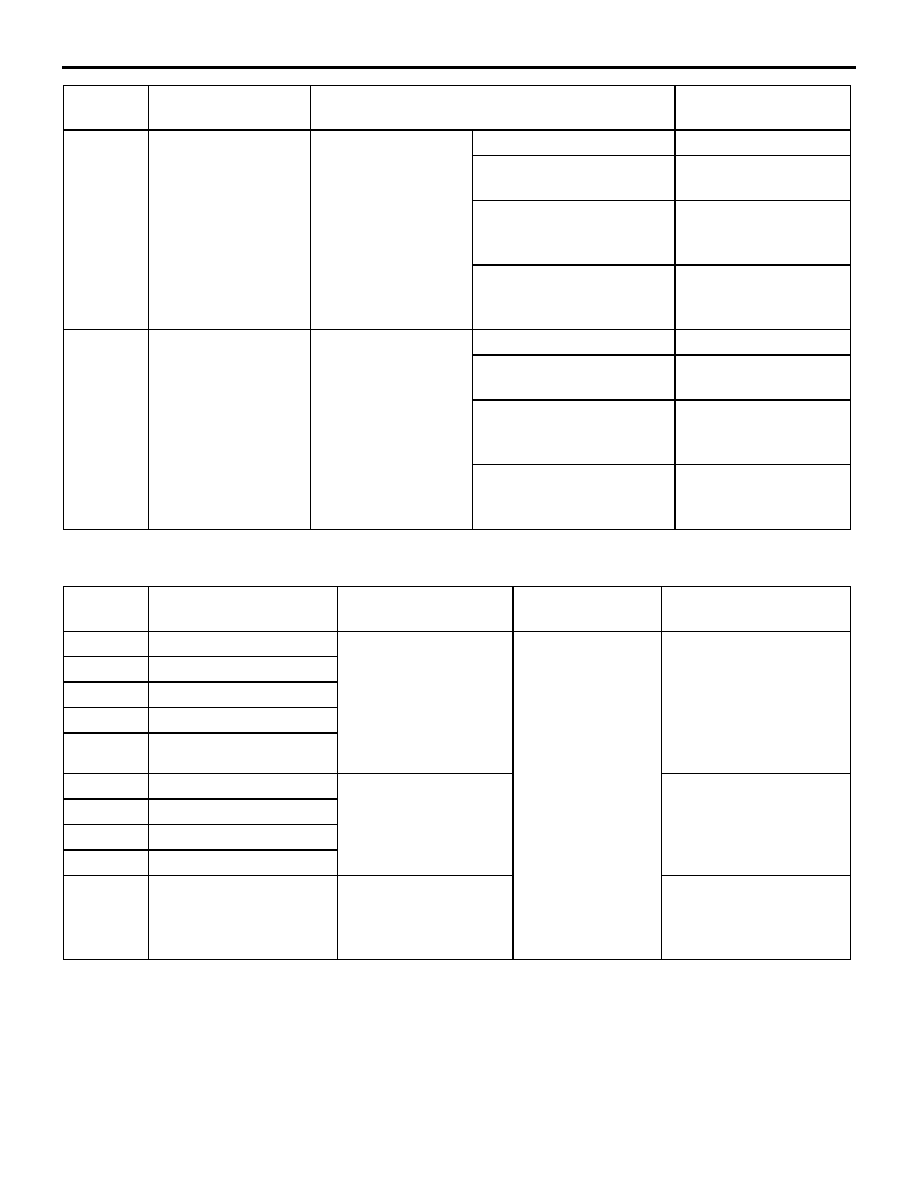
ACTUATOR TEST JUDGMENT VALUE

M1231008200345

68

Upshift switch

Ignition switch: ON
Engine: Stopped

Selector lever position: D

OFF

Selector lever position: 
Select sport mode

OFF

Selector lever position: 
Upshift and hold the 
selector lever

ON

Selector lever position: 
Downshift and hold the 
selector lever

OFF

69

Downshift switch

Ignition switch: ON
Engine: Stopped

Selector lever position: D

OFF

Selector lever position: 
Select sport mode

OFF

Selector lever position: 
Upshift and hold the 
selector lever

OFF

Selector lever position: 
Downshift and hold the 
selector lever

ON

Data list 
No.

Check item

Inspection conditions

Normal condition

Item No.

Inspection item

Test description

Inspection 
condition

Normal status

01

LR solenoid valve

Actuate solenoid valve 
indicated by MUT-II/III 
for 5 seconds at duty 
ratio of 50%.
Other remaining 
solenoid valve are not 
ON.

Ignition switch: ON
Selector lever 
position: P
Engine: Stopped
Accelerator pedal: 
Released

When solenoid valve is 
actuated, operating 
sound is audible.

02

UD solenoid valve

03

2ND solenoid valve

04

OD solenoid valve

06

DCC solenoid valve

07

1st indicator lamp

Illuminate shift 
indicator indicated by 
MUT-II/III for 3 
seconds

Shift indicator is 
displayed.

08

2nd indicator lamp

09

3rd indicator lamp

10

4th indicator lamp

12

A/T control relay

A/T control relay is 
OFF for three 
seconds.

Data list No.54
During test: 0 V
Normal: System voltage 
(V)

TROUBLESHOOTING <A/T>

AUTOMATIC TRANSMISSION (FF)

23A-136

INVECS-II CANCEL COMMAND

M1231009500327

CHECK AT ENGINE-A/T-ECU TERMINALS

M1231008400350

Item No.

Item

Contents

NOTE

14

INVECS-II

Stop the INVECS-II control and 
changes gear according to the 
standard shift pattern.

Use this procedure when carrying out road 
test procedure 8.
If the ignition switch is turned from OFF to 
ON to OFF, this function restores the 
INVECS-II control.

AC201888

1

2

3

4

5

6

7

8

9 10

12

11

13

14

15

16 17 18

19 20

21

22

23 24 25

26 27

31 32

33

34

35 36 37 38 39 40 41 42

43

44 45 46 47 48

50

51

52 53

54 55

49

56

57

58

61 62

63 64

65 66 67 68 69 70 71 72 73

74 75 76 77 78 79 80 81 82

83 84

85 86 87

88 89

91 92

93 94 95

96 97 98 99 100101102103

104

105106

107108109

110111112

113114

115116117

118119120

121122

123 124

125126127128129 130 131 132 133

134135

136137 138 139 140 141

142143

144

145 146

C-139

C-140

C-141

C-142

C-138

AI

Terminal 
No.

Check item

Inspection condition

Standard value

39

Stoplight switch

Ignition switch: ON

Brake pedal: Depressed

System voltage

Ignition switch: ON

Brake pedal: Released

1 V or less

64

Input shaft speed 
sensor

Measure between terminals 64 and 88 
with an oscilloscope.

Engine: 2,000 r/min

Selector lever position: Sport mode 
(3rd gear)

Refer to 

P.23A-139

Inspection Procedure 
Using an Oscilloscope.

66

Inhibitor awitch: P

Ignition switch: ON

Selector lever position: P

System voltage

Ignition switch: ON

Selector lever position: Other than 
above

1 V or less

67

Inhibitor awitch: R

Ignition switch: ON

Selector lever position: R

System voltage

Ignition switch: ON

Selector lever position: Other than 
above

1 V or less

68

Shift switch (Down)

Ignition switch: ON

Selector lever operation: Downshift and 
hold the selector lever

System voltage

Ignition switch: ON

Selector lever operation: Other than 
above

1 V or less

70

Crankshaft position 
sensor

Engine: Idling

1.5 

 2.5 V

TROUBLESHOOTING <A/T>

AUTOMATIC TRANSMISSION (FF)

23A-137

73

Output shaft speed 
sensor

Measure between terminals 73 and 88 
with an oscilloscope.

Engine: 2,000 r/min

Selector lever position: Sport mode 
(3rd gear)

Refer to 

P.23A-139

Inspection Procedure 
Using an Oscilloscope.

75

Inhibitor awitch: N

Ignition switch: ON

Selector lever position: N

System voltage

Ignition switch: ON

Selector lever position: Other than 
above

1 V or less

76

Inhibitor switch: D

Ignition switch: ON

Selector lever position: D

System voltage

Ignition switch: ON

Selector lever position: Other than 
above

1 V or less

77

Shift switch (Up)

Ignition switch: ON

Selector lever operation: Upshift and 
hold the selector lever

System voltage

Ignition switch: ON

Selector lever operation: Other than 
above

1 V or less

79

Vehicle speed signal

Measure between terminals 79 and 
ground with an oscilloscope.

Engine: 2,000 r/min

Selector lever position: Sport mode 
(3rd gear)

Refer to 

P.23A-139

Inspection Procedure 
Using an Oscilloscope.

85

Select switch

Ignition switch: ON

Selector lever position: Sport mode

System voltage

Ignition switch: ON

Selector lever position: Other than 
above

1 V or less

119

A/T fluid temperature 
sensor

A/T fluid temperature: 20

°

C

3.8 

 4.0 V

A/T fluid temperature: 40

°

C

3.2 

 3.4 V

A/T fluid temperature: 80

°

C

1.7 

 1.9 V

121

Shift indicator C

Measure the voltage when 
each shift range is displayed 
by using actuator function 
(item No.07 to 10) on the 
scan tool (MUT-II/III).

1st

1 V or less

2nd

1 V or less

3rd

1 V or less

4th

 10 V

123

Solenoid valve power 
supply

Ignition switch: LOCK (OFF)

1 V or less

Ignition switch: ON

System voltage

124

Solenoid valve power 
supply

Ignition switch: LOCK (OFF)

1 V or less

Ignition switch: ON

System voltage

Terminal 
No.

Check item

Inspection condition

Standard value

TROUBLESHOOTING <A/T>

AUTOMATIC TRANSMISSION (FF)

23A-138

125

Shift indicator B

Measure the voltage when 
each shift range is displayed 
by using actuator function 
(item No.07 to 10) on the 
scan tool (MUT-II/III).

1st

1 V or less

2nd

 10 V

3rd

 10 V

4th

1 V or less

127

A/T control relay

Always

1 V or less

128

LR solenoid valve

Engine: Idling

Selector lever position: P

System voltage

Engine: Idling

Selector lever position: Sport mode 
(2nd gear)

 9 V

130

DCC clutch solenoid 
valve

Engine: Idling

Selector lever position: P

System voltage

131

Ground

Always

1 V or less

134

Shift indicator A

Measure the voltage when 
each shift range is displayed 
by using actuator function 
(item No.07 to 10) on the 
scan tool (MUT-II/III).

1st

 10 V

2nd

1 V or less

3rd

 10 V

4th

1 V or less

135

A/T fluid temperature 
warning light

Ignition switch: LOCK (OFF) to ON

1 V or less to System 
voltage (after several 
seconds have elapsed)

136

2ND solenoid valve

Engine: Idling

Selector lever position: Sport mode 
(2nd gear)

System voltage

Engine: Idling

Selector lever position: P

 9 V

137

UD solenoid valve

Engine: Idling

Selector lever position: Sport mode 
(1st gear)

System voltage

Engine: Idling

Selector lever position: P

 9 V

138

OD solenoid valve

Engine: Idling

Selector lever position: Sport mode 
(3rd gear)

System voltage

Engine: Idling

Selector lever position: P

 9 V

139

Ground

Always

1 V or less

Terminal 
No.

Check item

Inspection condition

Standard value


Content   ..  208  209  210  211   ..