Mitsubishi Outlander (2003+). Manual - part 208


  Index      Mitsubishi     Mitsubishi Outlander - service repair manual 2003 year


Search            


Content   ..  206  207  208  209   ..


Mitsubishi Outlander (2003+). Manual - part 208


TROUBLESHOOTING <A/T>

AUTOMATIC TRANSMISSION (FF)

23A-127

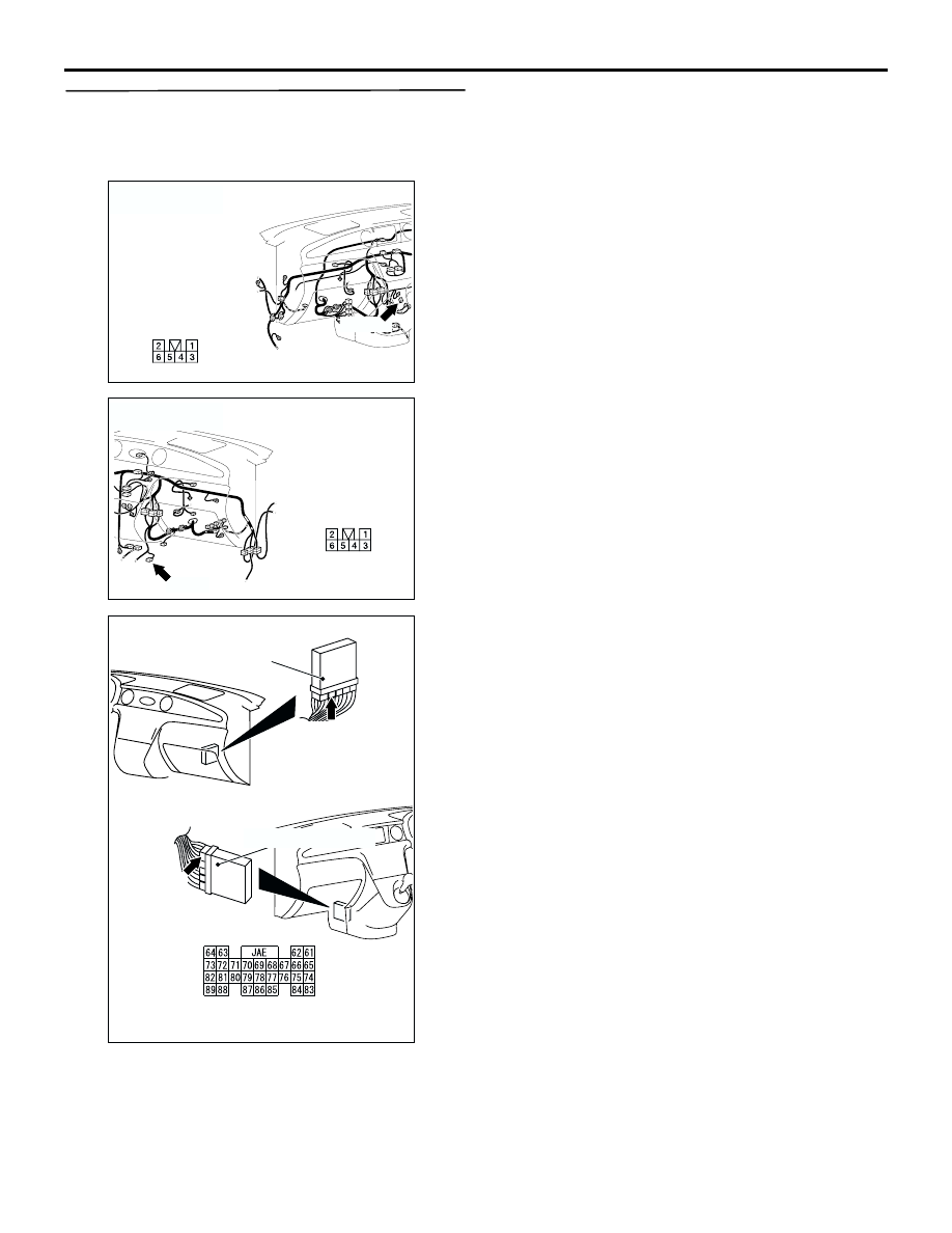
STEP 24. Check the harness between shift switch 
assembly connector C-129 <RHD>, C-143 <LHD> 
terminal No.5 and engine-A/T-ECU connector 
C-141 terminal No.68.

Check the output line for short-circuited or open 
circuit.

Q: Is the check result normal?

YES : 

Go to Step 4.

NO : 

Repair the wiring harness.

AC308735

BI

C-129

Harness side

Connector: C-129
<RHD>

AC308718

BD

C-143

Connector: C-143
<LHD>

Harness side

AC309479 AE

Connector: C-141 <LHD>

Connector: C-141 <RHD>

Engine-A/T-ECU

Harness side

Engine-A/T-ECU

C-141 (GR)

C-141 (GR)

TROUBLESHOOTING <A/T>

AUTOMATIC TRANSMISSION (FF)

23A-128

INSPECTION PROCEDURE 17: Abnormal shift indicator display

OPERATION
The engine-A/T-ECU detects the shift range (sport 
mode) which the driver has selected, and sends the 
information to the combination meter.

COMMENTS ON TROUBLE SYMPTOM
The cause is probably a malfunction of the shift 
switch assembly, combination meter and 
engine-A/T-ECU.

Possible causes

Malfunction of shift switch assembly

Malfunction of the combination meter

Damaged harness wires and connectors

Malfunction of the engine-A/T-ECU

DIAGNOSIS

STEP 1. MUT-II/III data list

Item 67: Select switch

Item 68: Upshift switch

Item 69: Downshift switch

Check the above data list 

P.23A-133

. (Refer to data 

list reference table.)

Q: Is the check result normal?

YES : 

Go to Step 2.

NO : 

Refer to inspection procedure 16: shift 
switch assembly system 

P.23A-114

.

STEP 2. Measure the voltage at engine-A/T-ECU 
connector C-138.
(1) Confirm the shift range by using the Actuator test 

on the MUT-II/III, and measure the voltage at the 

ENGINE-
A/T-ECU

Wire colour code
B : Black     LG : Light green     G : Green     L : Blue     W : White     Y : Yellow     SB : Sky blue
BR : Brown     O : Orange     GR : Gray     R : Red     P : Pink     V : Violet   

COMBINATION
METER

CONTROL CIRCUIT

AC309571

Shift indicator display system circuit

AB

TROUBLESHOOTING <A/T>

AUTOMATIC TRANSMISSION (FF)

23A-129

ECU terminals.

(2) Ignition switch: ON

Q: Is the check result normal?

YES : 

Go to Step 4.

NO : 

Go to Step 3.

STEP 3. Connectors check: C-138 
engine-A/T-ECU connector, C-105 intermediate 
connector, C-04 combination connector

Item 
No.

Gear 
shift 
position

Measured terminals
Between 
terminal 
134 and 
earth

Between 
terminal 
125 and 
earth

Between 
terminal 
121 and 
earth

09

3rd

 10 V

 10 V

1 V or 
less

10

4th

1 V or 
less

1 V or 
less

 10 V

AC309479

Engine-A/T-ECU

Harness side

C-138 (GR)

Engine-A/T-ECU

C-138 (GR)

124 123

130

131

132

133
141 140 139 138
146 145

129
137

128
136

127126

135
143

121
125
134
142

144

122

AC

Connector: C-138 <RHD>

Connector: C-138 <LHD>

AC309479

Engine-A/T-ECU

Harness side

C-138 (GR)

Engine-A/T-ECU

C-138 (GR)

124 123

130

131

132

133
141 140 139 138
146 145

129
137

128
136

127126

135
143

121
125
134
142

144

122

AC

Connector: C-138 <RHD>

Connector: C-138 <LHD>

AC308735

AW

C-105

Connector: C-105
<RHD>

10

1

21

16

13

4

11

2

12

3

1415

1718

5

20

7

19

6

8

22

9

AC308718

AR

C-105

Connector: C-105
<LHD>

10

1

21

16

13

4

11

2

12

3

1415

1718

5

20

7

19

6

8

22

9

TROUBLESHOOTING <A/T>

AUTOMATIC TRANSMISSION (FF)

23A-130

Check for the contact with terminals.

Q: Is the check result normal?

YES : 

Replace the engine-A/T-ECU.

NO : 

Repair the defective connector.

STEP 4. Measure the voltage at combination 
meter connector C-04.
(1) Remove the combination meter.

(2) Confirm the shift range by using the Actuator test 

on the MUT-II/III, and measure the voltage at the 
combination meter harness-side connector 
terminals.

(3) Ignition switch: ON

Q: Is the check result normal?

YES : 

Go to Step 7.

NO : 

Go to Step 5.

AC308769

AV

C-04

Connector: C-04
<RHD>

Harness side

41

52

40

51

39

50

38

49

37

48

36

47

35

46

34

45

33

44

32

43

31

42

AC308716

AS

C-04

Connector: C-04
<LHD>

Harness side

Item 
No.

Gear 
shift 
position

Measured terminals
Between 
terminal 
50 and 
earth

Between 
terminal 
51 and 
earth

Between 
terminal 
52 and 
earth

09

3rd

 10 V

 10 V

1 V or 
less

10

4th

1 V or 
less

1 V or 
less

 10 V

AC308769

AV

C-04

Connector: C-04
<RHD>

Harness side

41

52

40

51

39

50

38

49

37

48

36

47

35

46

34

45

33

44

32

43

31

42

AC308716

AS

C-04

Connector: C-04
<LHD>

Harness side


Content   ..  206  207  208  209   ..