Mitsubishi Outlander (2003+). Manual - part 181
TROUBLESHOOTING <A/T>
AUTOMATIC TRANSMISSION (FF)
23A-19
DIAGNOSTIC TROUBLE CODE
PROCEDURES
Code No.15: A/T fluid temperature sensor system
OPERATION
•
The A/T fluid temperature sensor converts the
automatic fluid temperature to voltage, and send
the information to the engine-A/T-ECU.
•
The A/T fluid temperature rises, the resistance
decreases. Thus, the sensor output voltage
depends on the automatic fluid temperature. As
the A/T fluid temperature rises, the output voltage
will decrease.
diagnosis code set conditions
If the A/T fluid temperature sensor output voltage is
4.5 volts or more after driving for 10 minutes or more,
there is an open circuit in the A/T fluid temperature
sensor and diagnosis code 15 is set.
Possible causes
•
Malfunction of the A/T fluid temperature sensor
•
Damaged harness wires and connectors
•
Malfunction of the engine-A/T-ECU
DIAGNOSIS
STEP 1. MUT-II/III data list
Item 15: A/T fluid temperature sensor (Refer to Data
List Table
Q: Is the check result normal?
YES :
Intermittent malfunction (Refer to GROUP
00
−
How to Cope with Intermittent
Malfunction
).
NO :
Go to Step 2.
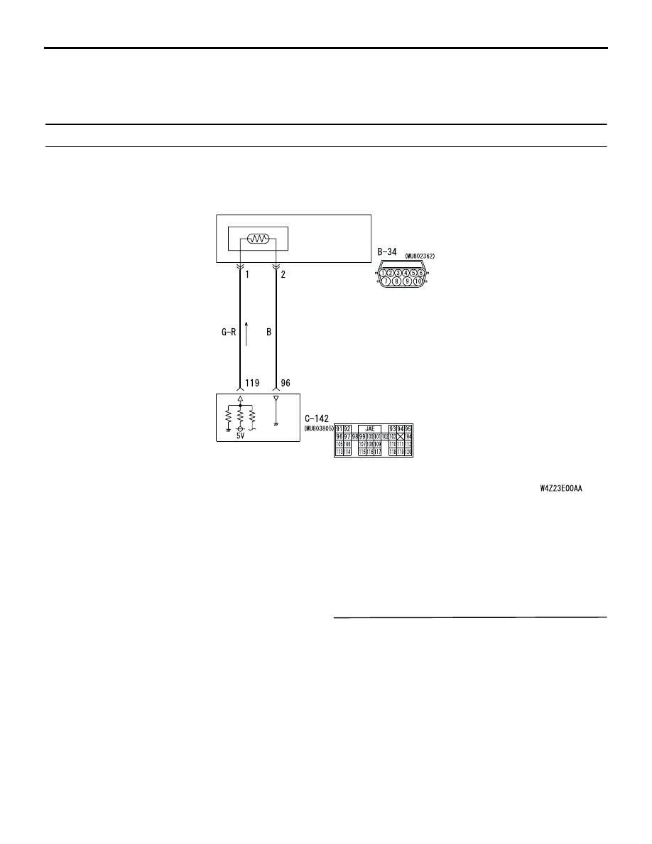
ENGINE-
A/T-ECU
A/T CONTROL
SOLENOID
VALVE ASSEMBLY
A/T
FLUID
TEMPERATURE
SENSOR
Wire colour code
B : Black LG : Light green G : Green L : Blue W : White Y : Yellow SB : Sky blue
BR : Brown O : Orange GR : Gray R : Red P : Pink V : Violet
AC309562 AC
A/T fluid temperature sensor system circuit