Mitsubishi Outlander (2003+). Manual - part 171


  Index      Mitsubishi     Mitsubishi Outlander - service repair manual 2003 year


Search            


Content   ..  169  170  171  172   ..


Mitsubishi Outlander (2003+). Manual - part 171


OUTPUT SHAFT

MANUAL TRANSMISSION OVERHAUL

22B-37

Installer-100 (MD998813)

Installer adapter (MD998819)

>>L<< SYNCHRONIZER SPRING INSTALLATION

Install the synchronizer spring onto the synchronizer 
ring as shown.

>>M<< SYNCHRONIZER RING INSTALLATION

CAUTION

There is a 5th speed synchronizer ring and a 
reverse synchronizer ring. Be careful not to 
confuse the two when installing, as a mistake can 
effect the shift feeling.

1. Check for the presence of identification notches 

on the synchronizer ring.

No notches: 5th speed synchronizer ring
Three notches: Reverse synchronizer ring 

2. Install the synchronizer ring so that it fits 

completely over the machined cone of the gear.

>>N<< 5TH SPEED-REVERSE SYNCHRONIZER 
HUB INSTALLATION
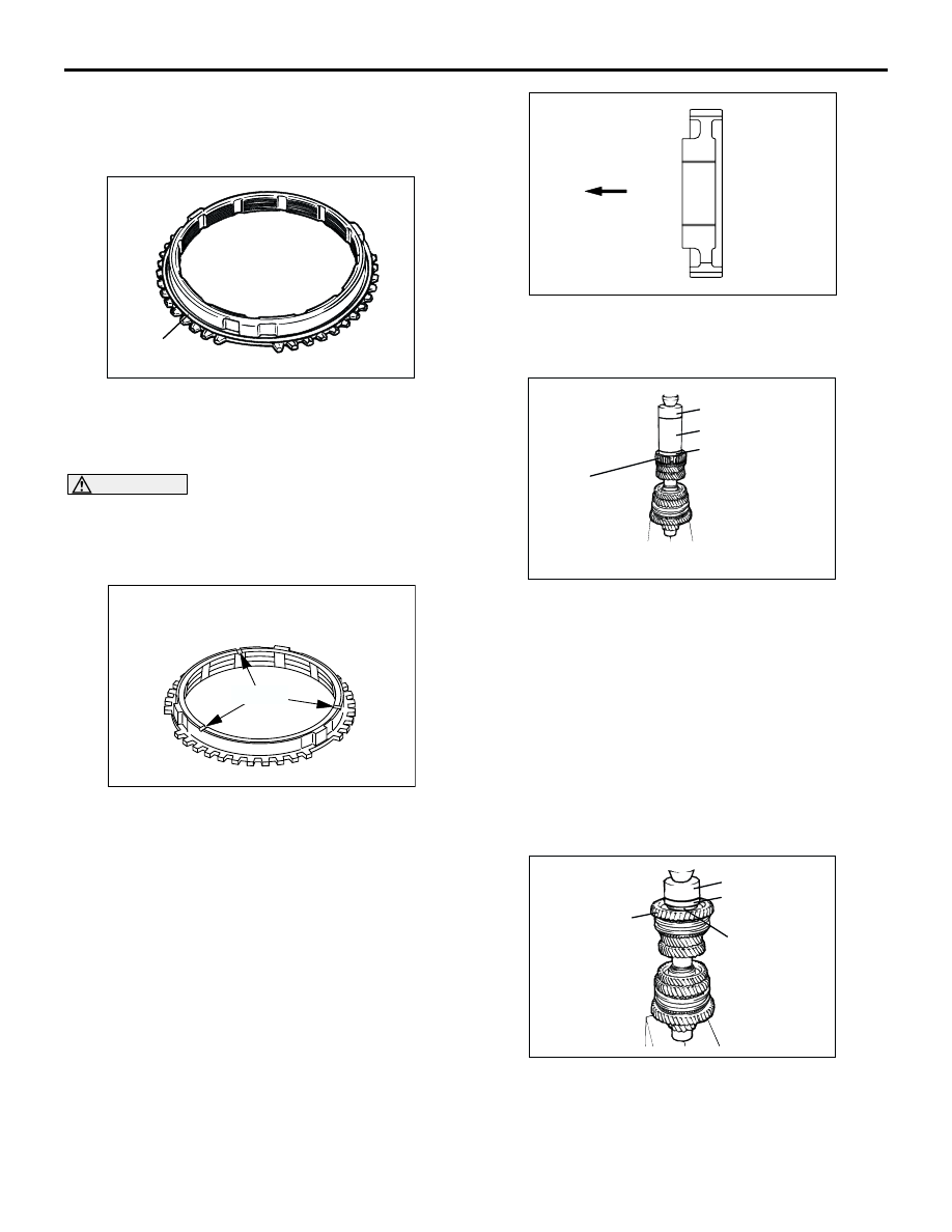
1. Set the output shaft on the press support stand.
2. Make sure that the synchronizer ring is fitted 

correctly on the cone of the 5th speed gear.

3. Check that the 5th speed-reverse synchronizer 

hub is oriented correctly for installation, and fit it 
on the output shaft.

4. Using special tools, press install the 5th 

speed-reverse synchronizer hub with the press.

Installer cap (MD998812)

Installer-100 (MD998813)

Installer adapter (MD998819)

5. Make sure that the synchronizer ring on the 5th 

speed gear side can rotate freely.

>>O<< REVERSE GEAR SLEEVE INSTALLATION
1. Make sure the synchronizer ring, reverse gear 

and needle roller bearing have been correctly 
installed.

2. Using special tools, press fit the reverse gear 

sleeve. Make sure that the reverse gear and the 
synchronizer ring can rotate freely during the 
pressing process.

Installer cap (MD998812)

AK204263

SYNCHRONIZER
SPRING

AB

Synchrnizer
spring

AK204393

Notch

AB

AK204306

Installation direction

AB

AK204228

MD998812

MD998813
MD998819

Synchronizer hub

AB

AK204270

MD998812
MD998818

Reverse
gear

Reverse gear
sleeve

AB

OUTPUT SHAFT

MANUAL TRANSMISSION OVERHAUL

22B-38

Installer adapter (MD998818)

>>P<< BALL BEARING INSTALLATION
1. Check the installation direction of the ball bearing.

2. Using special tools, install the ball bearing with the 

press.

Installer cap (MD998812)

Installer adapter (MD998818)

>>Q<< SNAP RING INSTALLATION

1. Install the thickest snap ring that can be fitted in 

the groove of output shaft.

2. Make sure that the rear bearing end play meets 

the standard value.

Standard value: 0 

 0.09 mm

INSPECTION

M1222002300131

OUTPUT SHAFT

1. Check the splines for damage and wear.
2. Check that the helical gear teeth surfaces are not 

damaged or worn.

NEEDLE ROLLER BEARING
1. Combine the needle roller bearing with the 

bearing sleeve and gear, and check that it rotates 
smoothly without noise or play.

2. Check the needle roller bearing cage for 

deformation.

SYNCHRONIZER RING

1. Check if the clutch gear teeth are damaged or 

broken.

2. Check internal surface for damage, wear and 

broken threads.

3. Force the synchronizer ring toward the clutch gear 

and check clearance "A". If "A" is less than the 
limit, replace the synchronizer ring.

Minimum limit: 0.5 mm

AK204271

MD998812

MD998818

Ball bearing

AC

AK204272 AC

Snap ring

AK204310AB

AK204298AB

AK204307

A

Gear

Synchronizer
ring

AB

OUTPUT SHAFT

MANUAL TRANSMISSION OVERHAUL

22B-39

OUTER SYNCHRONIZER RING/INNER 
SYNCHRONIZER RING/SYNCHRONIZER CONE 
<FOR 1ST, 2ND SPEED>

CAUTION

When replacing, replace the outer ring, inner ring 
and cone as a set.

1. Check that the clutch gear tooth surfaces and 

cone surfaces are not damaged or broken.

2. Install the outer ring, inner ring and cone, force 

them toward the gear, and check clearance "A". If 
"A" is less than the limit, replace them as a set.

Minimum limit: 0.5 mm

SYNCHRONIZER SLEEVE AND HUB

1. Combine the synchronizer sleeve and hub, and 

check that they slide smoothly.

2. Check that the sleeve is free from damage at its 

inside splines ends.

SYNCHRONIZER SPRING

Check that the spring is not sagging, deformed or 
broken.

SPEED GEARS

1. Check that the helical and clutch gear tooth 

surfaces are not damaged or worn.

2. Check that the synchronizer cone surfaces are 

not roughened, damaged or worn.

3. Check that the gear inside diameter and front and 

rear surfaces are not damaged and worn.

AK204395AB

AK203130AD

A

Outer ring

Inner ring

Cone

Gear

AK204217

Sleeve

Hub

AB

AK204314AB

AK204299AB

REVERSE IDLER GEAR

MANUAL TRANSMISSION OVERHAUL

22B-40

REVERSE IDLER GEAR

DISASSEMBLY AND REASSEMBLY

M1222012500136

REASSEMBLY SERVICE POINT

>>A<< FRICTION DAMPER INSTALLATION

After apply gear oil to the outside and inside 
circumferences of the friction damper, install it using 
the special tool in position as shown in Fig.

AK302745AC

Apply gear oil to
all moving parts
before installation.

1

2

3

4

5

6

Disassembly steps

1.

Snap ring

2.

Thrust washer

3.

Reverse idler gear

4.

Needle roller bearing

>>A<<

5.

Friction damper

6.

Reverse idler gear shaft

AK302712

21.5 ± 0.2 mm

AB


Content   ..  169  170  171  172   ..