Mitsubishi Outlander (2003+). Manual - part 161


  Index      Mitsubishi     Mitsubishi Outlander - service repair manual 2003 year


Search            


Content   ..  159  160  161  162   ..


Mitsubishi Outlander (2003+). Manual - part 161


TRANSMISSION ASSEMBLY

MANUAL TRANSMISSION (FF)

22A-15

TRANSMISSION ASSEMBLY

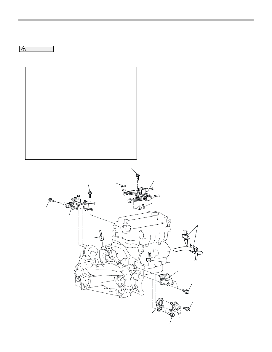
REMOVAL AND INSTALLATION

M1221002700318

CAUTION

*: Indicates parts which should be temporarily tightened, and then fully tightened after installing the 
engine into the vehicle.

Pre-removal and Post-installation Operation

Air Cleaner assembly, Air Cleaner Bracket Removal and 
Installation (Refer to GROUP 15, Air Cleaner 

P.15-3

<4G63>, 

P.15-4

<4G69>).

Battery and Battery Tray Removal and Installation.

Front Under Cover Removal and Installation (Refer to 

GROUP 51, Front Bumper 

P.51-3

).

Side Under Cover Removal and Installation (Refer to 

GROUP 51, Front Bumper 

P.51-3

).

Transfer Oil Draining and Supplying <4WD> (Refer to 

P.22A-8

).

Drive Shaft Removal and Installation (Refer to GROUP 26 

P.26-15

).

Output Shaft Removal and Installation <4WD> (Refer to 

GROUP 26 

P.26-15

).

Front Exhaust Pipe Removal and Installation (Refer to 

GROUP 15, Exhaust Pipe and Main Muffle

P.15-13

).

Propeller Shaft Removal and Installation <4WD> (Refer to 

GROUP 25 

P.25-3

).

AC210287AB

<4WD>

<2WD>

70 ± 10 N·m

70 ± 10 N·m

70 ± 10 N·m

18 ± 3 N·m

18 ± 3 N·m

1

2

3

4

5

5

6

18 ± 3 N·m

7

7

8

TRANSMISSION ASSEMBLY

MANUAL TRANSMISSION (FF)

22A-16

Removal steps

1.

Transmission harness clamp

2.

Back-up lamp switch connector

3.

Vehicle speed sensor connector

4.

Clutch release cylinder and clutch 
oil pipe

5.

Snap pin

6.

Cable bracket and cable assembly 
<Transmission side>

Transfer assembly (Refer to 

P.22A-13

).

7.

Rear roll mount bracket

8.

Rear roll mount adapter bracket 
<4WD>

<<A>>

Engine and transmission 
assembly supporting

Removal steps (Continued)

AC210288

<4WD>

<2WD>

AB

13

14

14

9.0 ± 1.0 N·m

9.0 ± 1.0 N·m

26 ± 5 N·m

44 ± 10 N·m

22 ± 4 N·m

15

48 ± 5 N·m

48 ± 5 N·m

48 ± 5 N·m

9

48 ± 5 N·m

9

9

48 ± 5 N·m

10

11

12

11

16

47 ± 7 N·m*

82 ± 7 N·m*

Removal steps

9.

Transmission assembly upper part 
coupling bolts

Starter coupling bolts (Refer to 
GROUP 16 

P.16-22

<4G63>, 

P.16-23

<4G69> ).

<<A>>

10. Transmission mounting assembly

>>B<<

11. Transmission mounting stopper
12. Transmission mounting

<<B>>

Engine assembly supporting

<<C>>

Clutch release bearing connection

>>A<<

13. Transmission housing front lower 

cove stay <4WD>

14. Flywheel housing front lower 

cover

15. Transmission assembly lower part 

coupling bolts

16. Transmission assembly

Removal steps (Continued)

TRANSMISSION ASSEMBLY

MANUAL TRANSMISSION (FF)

22A-17

REMOVAL SERVICE POINTS

<<A>> ENGINE AND TRANSMISSION ASSEMBLY 
SUPPORTING/TRANSMISSION MOUNT 
ASSEMBLY REMOVAL

While supporting the engine and transmission 
assembly with a garage jack, remove the 
transmission mount assembly.

<<B>> ENGINE ASSEMBLY SUPPORT

1. <Engine hanger (special tool MB991895) is used>

(1) Set special tool MB991895 to the strut 

mounting nuts and the radiator support upper 
insulator mounting bolts, which are located in 
the engine compartment, as shown.

(2) Set special tools MB991454 to hold the 

engine/transmission assembly.

2. <Engine hanger (special tool MB991928) is used>

(1) Assemble the engine hanger (special tool 

MB991928). Set following parts to the base 
hanger.

Slide bracket (HI)

Foot (standard) (MB991932)

Joint (90) (MB991930)

Joint (50) (MB991929)

(2) Set the engine hanger (special tool 

MB991928) to the strut mounting nuts and the 
radiator support upper insulator mounting 
bolts, which are located in the engine 
compartment, as shown.

NOTE: Adjust the engine hanger balance by 
sliding the slide bracket (HI).

(3) Set special tools MB991454 to hold the 

engine/transmission assembly.

AC210384

Garage jack

Engine and transmission assembly

AB

AC210400AB

AC210388 AB

MB991527

MB991454

MB991895

AC212277

Front side

Slide 
bracket 
(HI)

Joint (50)
(MB991929)

Joint (90)
(MB991930)

Foot (Standard)
(MB991932)

Foot (Standard)
(MB991932)

AD

AC210400AB

AC210392

MB991928

Slide bracket (HI)

MB991929

MB991932

MB991932

MB991930

MB991934

MB991527

MB991454

AF

TRANSMISSION ASSEMBLY

MANUAL TRANSMISSION (FF)

22A-18

<<C>> CLUTCH RELEASE BEARING 
SEPARATION

CAUTION

If it is hard to turn the screwdriver (to pry off the 
release bearing), remove the screwdriver once 
and repeat the below procedure after pushing the 
release fork fully in the direction a two or three 
times. Forcibly prying can cause the release 
bearing to be damaged.
1. Remove the cover from the service hole in the 

clutch housing.

2. While pushing the release fork by hand in the 

direction A, insert a flap-tip screwdriver between 
the release bearing and the wedge collar.

CAUTION

Be sure to push the release fork in the direction 
A before inserting a screwdriver.
3. Separate the release bearing from the wedge 

collar by prying with the screwdriver (turning the 
screwdriver grip 90

°

).

NOTE: The release fork is forced to move fully in 
the direction B by the return spring as soon as it is 
separated from the wedge collar.

INSTALLATION SERVICE POINTS

>>A<< TRANSMISSION HOUSING FRONT 
LOWER COVER STAY INSTALLATION
Install the transmission housing front lower cove stay 
as below.
1. Tighten the engine-side bolts to the specified 

torque.

Tightening torque: 22 

±

 4 N

m

2. Tighten the transmission-side bolts to the 

specified torque.

Tightening torque: 44 

±

 10 N

m

>>B<< TRANSMISSION MOUNTING STOPPER 
INSTALLATION

Install the transmission mounting stopper so that the 
arrow points as shown in the illustration.

AC210561AC

Wedge collar

Release bearing

A

B

Service hole

Release fork

AC210408

Transmission
mounting stopper

Arrow

Transmission
mounting

Engine side

AC


Content   ..  159  160  161  162   ..