Mitsubishi Outlander (2003+). Manual - part 138


  Index      Mitsubishi     Mitsubishi Outlander - service repair manual 2003 year


Search            


Content   ..  136  137  138  139   ..


Mitsubishi Outlander (2003+). Manual - part 138


CHARGING SYSTEM

ENGINE ELECTRICAL

16-17

DISASSEMBLY SERVICE POINTS

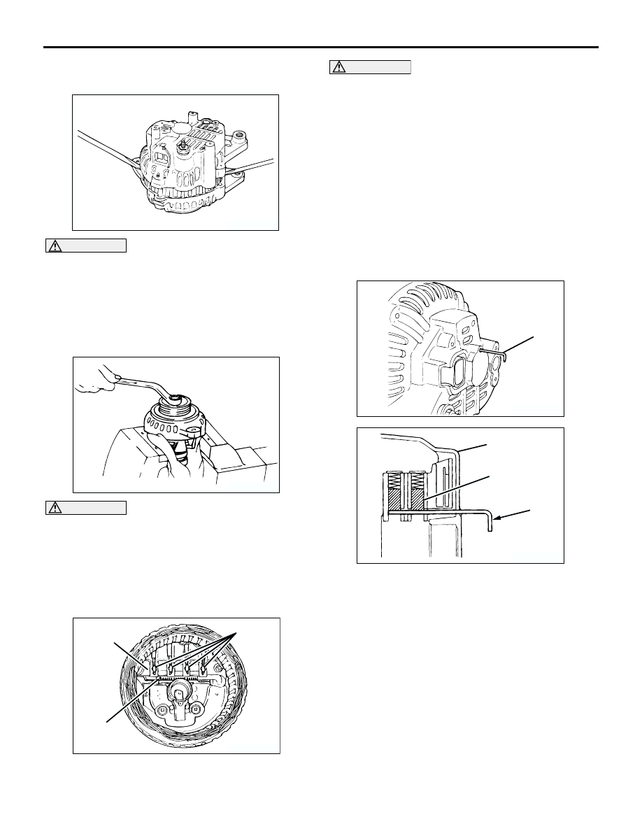
<<A>>FRONT BRACKET ASSEMBLY REMOVAL

CAUTION

Do not insert the screwdriver blades too deep. 
Doing so could damage the stator coil.
Insert the blades of screwdrivers between the front 
bracket assembly and stator core, and pry and 
separate them with the screwdrivers.

<<B>>ALTERNATOR PULLEY REMOVAL

CAUTION

Perform operation carefully not to damage the 
rotor.
Clamp the rotor in a vise with the pulley facing up to 
remove the pulley.

<<C>>STATOR / REGULATOR ASSEMBLY 
REMOVAL

CAUTION

Use a 180 

 250 W soldering iron, and finish 

unsoldering within four seconds. Diodes will 
be damaged by heat if unsoldering time is too 
long.

Avoid applying undue force to the diode 
leads.

1. Unsolder the stator leads from the main diode of 

the rectifier assembly when the stator is removed.

2. When removing the rectifier assembly from the 

regulator assembly, undo the soldered points on 
the rectifier assembly.

REASSEMBLY SERVICE POINTS

>>A<<REGULATOR ASSEMBLY INSTALLATION

After installing the regulator assembly, insert a piece 
of wire through the hole in the rear bracket while 
pressing the brush to keep the brush against 
movement.
NOTE: Holding the brush with the wire facilities 
installation of the rotor.

AK202718

AK202714

AK202778

Solder

Solder

Rectifier 
assembly

AB

AK202779

Wire

AB

AK202830

Rear bracket

Brush

Wire

AB

CHARGING SYSTEM

ENGINE ELECTRICAL

16-18

>>B<<ROTOR INSTALLATION

Remove the brush holding wire after the rotor has 
been installed.

INSPECTION 

M1161001700129

ROTOR

1. Measure the resistance between the two slip rings 

of the rotor coil to check the continuity between 
them.
Replace the rotor if the resistance is not within the 
standard value range.

Standard value: 3 

 5 

2. Check the continuity between the slip rings and 

core.

3. If continuity is present, replace the rotor.

STATOR

1. Check the continuity between coil leads.

If there is no continuity, replace the stator.

2. Check the continuity between coil and core.

If there is no continuity, replace the stator.

RECTIFIER ASSEBMLY

1. Check the condition of the (+) heat sink by 

checking continuity between the (+) heat sink and 
each of the stator coil lead connecting terminals.
If continuity is present for both terminals, the 
diode is shorted. Replace the rectifier assembly.

AK202779

Wire

AB

AK202735

AK202736

AK202716

AK202717

AK202803

CHARGING SYSTEM

ENGINE ELECTRICAL

16-19

2. Check the condition of the (

) heat sink by 

checking continuity between the (

) heat sink and 

each of the stator coil lead connecting terminals.
If continuity is present in both directions, the diode 
is shorted. Replace the rectifier assembly.

3. Check the condition of the diode trio by testing 

continuity of each of the three diodes using a 
circuit tester connected to both sides of the diode. 
Connect in a polarity and then reverse the polarity 
for each test.
If continuity exists or no continuity exists for both 
polarities, the diode is defective. Replace the 
rectifier assembly if any of the diodes is defective.

BRUSH

1. Measure the length of the protrusion of the brush. 

Replace the brush if the protrusion length is 
shorter than the limit.

Limit: 2 mm minimum

2. Unsolder the lead of the brush. The brush will 

come out, becoming ready for removal.

3. Install a new brush by pushing it into the holder as 

shown in the drawing and soldering the lead.

AK202802

AK202804

AK202808

Protrusion
length

AB

AK202834

Solder

AB

STARTING SYSTEM

ENGINE ELECTRICAL

16-20

STARTING SYSTEM

GENERAL INFORMATION

M1162000100268

If the ignition switch is turned to the "START" 
position, current flows in the pull-in and holding coils 
provided inside magnetic switch, attracting the 
plunger, When the plunger is attracted, the lever 
connected to the plunger is actuated to engage the 
starter clutch.
On the other hand, attracting the plunger will turn on 
the magnetic switch, allowing the "B" terminal and 
"M" terminal to conduct. Thus, current flows to 
engage the starter motor.

When the ignition switch is returned to the "ON" 
position after starting the engine, the starter clutch is 
disengaged from the ring gear.
An overrunning clutch is provided between the pinion 
and the armature shaft, to prevent damage to the 
starter.

SYSTEM DIAGRAM

AK202970

Pull-in coil

Holding coil

Plunger

Lever

Pinion gear

Overrunning clutch

Yoke

Brush

Armature

Ignition switch

Battery

+

AB

B

M

S


Content   ..  136  137  138  139   ..