Mitsubishi Outlander (2003+). Manual - part 105


  Index      Mitsubishi     Mitsubishi Outlander - service repair manual 2003 year


Search            


Content   ..  103  104  105  106   ..


Mitsubishi Outlander (2003+). Manual - part 105


TROUBLESHOOTING

MULTIPORT FUEL INJECTION (MFI)

13A-283

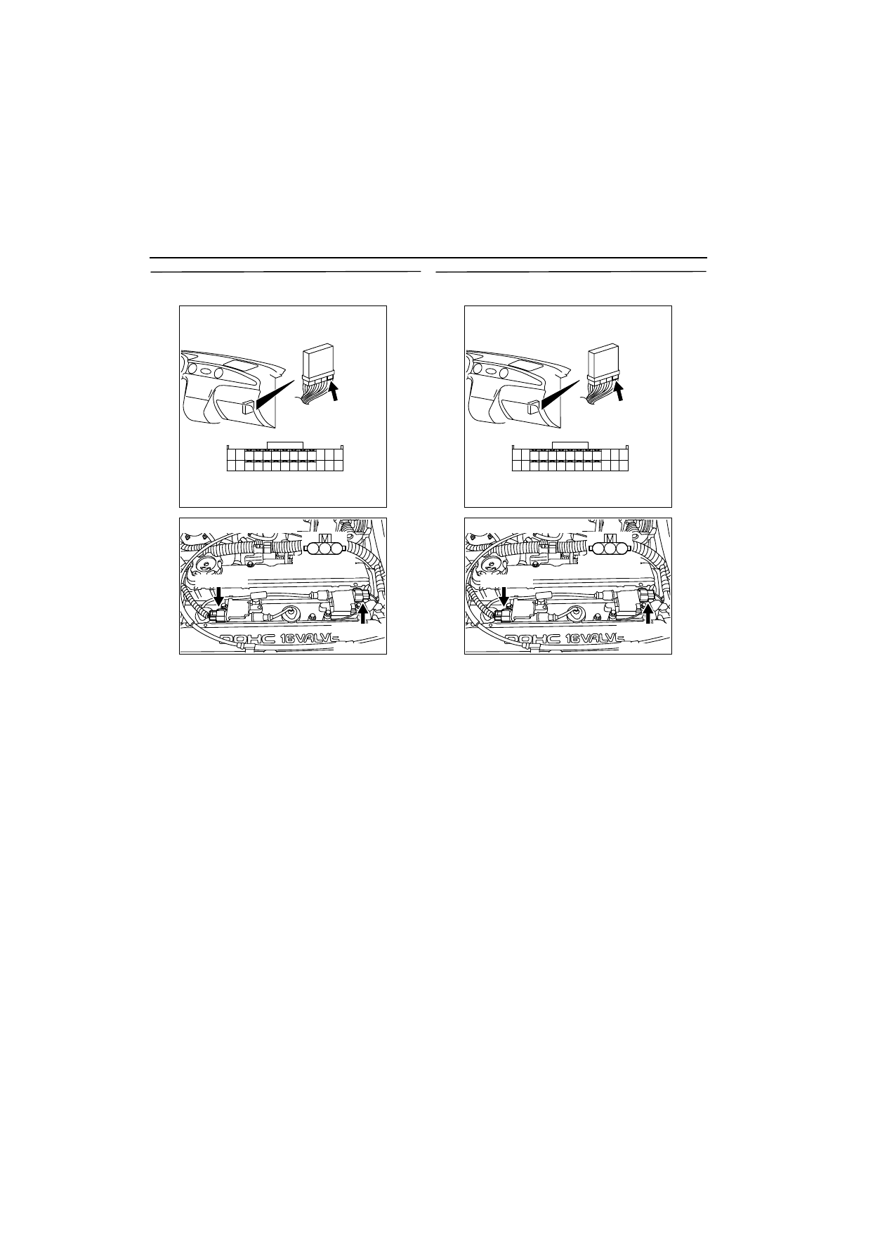
STEP 8. Measure voltage at C-134 engine-ECU 
connector.

œ

Measure engine-ECU terminal voltage.

œ

Disconnect B-111 and B-110 ignition coil connec-
tors.

œ

Engine: Cranking

œ

Voltage between terminal No. 10 and earth, also 
between terminal No. 23 and earth.

OK: 0.5 

-

 4.0 V

Q: Is the check result normal? 

YES : 

Go to Step 9 .

NO : 

Go to Step 10 .

STEP 9. Connector check: C-134 engine-ECU 
connector

Q: Is the check result normal? 

YES : 

Check and repair harness between B-111 

(terminal No. 3) ignition coil connector and 
C-134 (terminal No. 23) engine-ECU 
connector, also between B-110 (terminal 
No. 3) ignition coil connector and C-134 
(terminal No. 10) engine-ECU connector.

œ

Check output line for open circuit.

NO : 

Repair.

AK300257

1

14

4

19

5

22

6

17

8

15

9

18

7

20

16

2

13 12

23

24

25

26

21

3

10

11

AB

CONNECTOR: C-134

C-134

Harness side connector

AK300308

1

2

3

AB

Harness side 
connector

B-111 (GR)

B-110 (GR)

Connector: B-110, B-111

AK300257

1

14

4

19

5

22

6

17

8

15

9

18

7

20

16

2

13 12

23

24

25

26

21

3

10

11

AB

CONNECTOR: C-134

C-134

Harness side connector

AK300308

1

2

3

AB

Harness side 
connector

B-111 (GR)

B-110 (GR)

Connector: B-110, B-111

TROUBLESHOOTING

MULTIPORT FUEL INJECTION (MFI)

13A-284

STEP 10. Connector check: C-134 engine-ECU 
connector

Q: Is the check result normal? 

YES : 

Go to Step 11 .

NO : 

Repair.

STEP 11. Check harness between B-111 (terminal 
No. 3) ignition coil connector and C-134 (terminal 
No. 23) engine-ECU connector, also between B-
110 (terminal No. 3) ignition coil connector and 
C-134 (terminal No. 10) engine-ECU connector.

œ

Check output line for short circuit.

Q: Is the check result normal? 

YES : 

Go to Step 12 .

NO : 

Repair.

STEP 12. Check the trouble symptoms.

Q: Does trouble symptom persist?

YES : 

Replace engine-ECU.

NO : 

Intermittent malfunction (Refer to GROUP 
00 

-

 How to Use 

Troubleshooting/Inspection Service Points 

3

00


).

AK300257

1

14

4

19

5

22

6

17

8

15

9

18

7

20

16

2

13 12

23

24

25

26

21

3

10

11

AB

CONNECTOR: C-134

C-134

Harness side connector

AK300257

1

14

4

19

5

22

6

17

8

15

9

18

7

20

16

2

13 12

23

24

25

26

21

3

10

11

AB

CONNECTOR: C-134

C-134

Harness side connector

AK300308

1

2

3

AB

Harness side 
connector

B-111 (GR)

B-110 (GR)

Connector: B-110, B-111

TROUBLESHOOTING

MULTIPORT FUEL INJECTION (MFI)

13A-285

STEP 13. Measure resistance at B-111 and B-110 
ignition coil connectors.

œ

Disconnect connector, and measure at harness 
side.

œ

Resistance between terminal No. 2 and earth.

OK: 2 

W

 or less

Q: Is the check result normal? 

YES : 

Go to Step 14 .

NO : 

Check and repair harness between B-111 

(terminal No. 2) ignition coil connector and 
body earth, also between B-110 (terminal 
No. 2) ignition coil connector and body 
earth.

œ

Check earthing line for open circuit 
and damage.

STEP 14. Check harness between C-303 (terminal 
No. 2) ignition switch connector and B-111 
(terminal No. 1) ignition coil connector, also 
between C-303 (terminal No. 2) ignition switch 
connector and B-110 (terminal No. 1) ignition coil 
connector.

NOTE: Before checking harness, check intermediate 
connectors A-14, C-116, C-203 and C-205, and 
repair if necessary.

œ

Check power supply line for damage.

Q: Is the check result normal? 

YES : 

Go to Step 15 .

NO : 

Repair.

AK300308

1

2

3

AB

Harness side 
connector

B-111 (GR)

B-110 (GR)

Connector: B-110, B-111

1

2

3

4

5

6

AK300304

CONNECTOR: C-303

C-303

Harness side
connector

AB

AK300308

1

2

3

AB

Harness side 
connector

B-111 (GR)

B-110 (GR)

Connector: B-110, B-111

TROUBLESHOOTING

MULTIPORT FUEL INJECTION (MFI)

13A-286

STEP 15. Check harness between B-111 (terminal 
No. 3) ignition coil connector and C-134 (terminal 
No. 23) engine-ECU connector, also between B-
110 (terminal No. 3) ignition coil connector and C-
134 (terminal No. 10) engine-ECU connector.

œ

Check output line for damage.

Q: Is the check result normal? 

YES : 

Go to Step 12 .

NO : 

Repair.

AK300308

1

2

3

AB

Harness side 
connector

B-111 (GR)

B-110 (GR)

Connector: B-110, B-111

AK300257

1

14

4

19

5

22

6

17

8

15

9

18

7

20

16

2

13 12

23

24

25

26

21

3

10

11

AB

CONNECTOR: C-134

C-134

Harness side connector


Content   ..  103  104  105  106   ..