Mitsubishi Outlander (2003+). Manual - part 94


  Index      Mitsubishi     Mitsubishi Outlander - service repair manual 2003 year


Search            


Content   ..  92  93  94  95   ..


Mitsubishi Outlander (2003+). Manual - part 94


TROUBLESHOOTING

MULTIPORT FUEL INJECTION (MFI)

13A-239

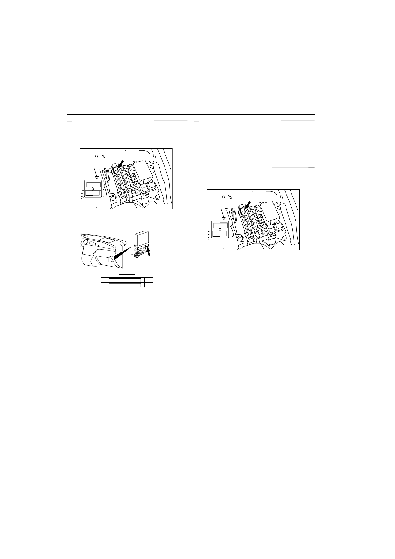
STEP 17. Check harness between B-17X 
(terminal No. 1) engine control relay connector 
and C-134 (terminal No. 12 and No. 25) engine-
ECU connector.

NOTE: Before checking harness, check intermediate 
connector C-17, and repair if necessary.

œ

Check output line for open/short circuit and dam-
age.

Q: Is the check result normal?

YES : 

Go to Step 18 .

NO : 

Repair.

STEP 18. Check engine control relay output 
power supply harness and connector for short 
circuit.

Q: Is the check result normal?

YES : 

Go to Step 19 .

NO : 

Repair.

STEP 19. Check harness between B-17X 
(terminal No. 3 and No. 4) engine control relay 
connector and battery.

NOTE: Before checking harness, check intermediate 
connector A-14, and repair if necessary.

œ

Check power supply line for damage.

Q: Is the check result normal?

YES : 

Go to Step 20 .

NO : 

Repair.

AK300255

2

1

3

4

Relay box’s
triangle marks

AB

CONNECTOR: B-17X

B-17X

Harness side
connector

AK300257

1

14

4

19

5

22

6

17

8

15

9

18

7

20

16

2

13 12

23

24

25

26

21

3

10

11

AB

CONNECTOR: C-134

C-134

Harness side connector

AK300255

2

1

3

4

Relay box’s
triangle marks

AB

CONNECTOR: B-17X

B-17X

Harness side
connector

TROUBLESHOOTING

MULTIPORT FUEL INJECTION (MFI)

13A-240

STEP 20. Check harness between B-17X 
(terminal No. 2) engine control relay connector 
and C-135 (terminal No. 38) engine-ECU 
connector.

œ

Check earthing line for damage.

Q: Is the check result normal?

YES : 

Go to Step 16 .

NO : 

Repair.

AK300255

2

1

3

4

Relay box’s
triangle marks

AB

CONNECTOR: B-17X

B-17X

Harness side
connector

AK300256

34 33 32

36 35

37

42

45

31

39

38

46

40

41

43

44

AB

CONNECTOR: C-135

C-135

Harness side connector

TROUBLESHOOTING

MULTIPORT FUEL INJECTION (MFI)

13A-241

Inspection Procedure 24: Fuel Pump System

AK300311

1 2 3

4

4 5 6

1 2 3

5

3 4

1 2

3 4

1 2

1

14

4

19

5

22

6

17

8

15

9

18

7

20

16

2

13

12

23 24 25 26

21

3

10 11

IG2

ST

LOCK

ACC

IG1

R

M

24

15A

8

7.5A

C-303

J/B

Ignition switch

Reray box

Engine-ECU

Fuel 
pump 
relay (1)
C-215

Fuel 
pump 
relay (2)
C-213

Fuel pump

8

2

41

      D-16 
(MU802058)

1

14

11

5

4

4

C-134

Fuel pump circuit

OFF

4

2

2

L-B

W

W

C-116

C-202

W

C-203

6

1

3

OFF

ON

ON

1

2

4

3

Battery

C-213

C-215

22

6

C-209

D-24

D-24

C-205

B

B-L

B-L

B

B

G

G

C-205

Wire colour code
B: Black  LG: Light green  G: Green  L: Blue  W: White  Y: Yellow  SB: Sky blue  BR: Brown  O: Orange  GR: Gray
R: Red  P: Pink  V:Violet

AB

TROUBLESHOOTING

MULTIPORT FUEL INJECTION (MFI)

13A-242

OPERATION

œ

The battery voltage is applied to the fuel pump 
relay (1) (terminal No. 3) form the ignition switch 
and is earthed to the vehicle body from the fuel 
pump relay (1) (terminal No. 2).

œ

The battery voltage is applied to the fuel pump 
relay (1) (terminal No. 4) and to the fuel pump 
relay (2) (terminal No. 1) from the fuel pump relay 
(1) (terminal No. 1).

œ

The battery voltage is applied to the fuel pump 
relay (2) (terminal No. 3) from the ignition switch. 
The engine-ECU (terminal No. 22) makes the 
power transistor in the unit be in "ON" position 
and makes currents go on the fuel pump relay (2) 
coil, and that makes the relay be in "ON" position.

œ

When the fuel pump relay (2) is in "ON" position, 
the battery voltage is supplied to the fuel pump 
(low pressure) from the fuel pump relay (2) (ter-
minal No. 4).

FUNCTION

œ

When the ignition switch ON signal is input to the 
engine-ECU, the engine-ECU places the fuel 
pump relay in the "ON" position. Accordingly, the 
battery voltage is supplied to the fuel pump.

PROBABLE CAUSE

œ

Failed fuel pump relay 

œ

Failed fuel pump

œ

Open/short circuit in fuel pump drive circuit or 
loose connector contact

œ

Failed engine-ECU

DIAGNOSIS PROCEDURE

STEP 1. Connector check: C-215 fuel pump relay 
(1) connector and C-213 fuel pump relay (2) 
connector

Q: Is the check result normal?

YES : 

Go to Step 2 .

NO : 

Repair.

STEP 2. Check fuel pump relay.

œ

Fuel pump relay, continuity check (Refer to 

3

13A


).

Q: Is the check result normal?

YES : 

Go to Step 3 .

NO : 

Replace fuel pump relay.

STEP 3. Measure resistance at C-215 fuel pump 
relay (1) connector.

œ

Remove relay, and measure at junction block 
side.

œ

Resistance between terminal No. 2 and earth.

OK: 2 

W

 or less

Q: Is the check result normal? 

YES : 

Go to Step 4 .

NO : 

Check intermediate connector C-205, and 

repair if necessary. If intermediate 
connector is normal, check and repair 
harness between C-215 (terminal No. 2) 
fuel pump relay (1) connector and body 
earth.

œ

Check earthing line for open circuit 
and damage.

AK300312

2 1

3

4

AB

CONNECTOR: C-213, C-215

C-213

C-215

Harness side
connector

Junction block’s
triangle marks

AK300313

2 1

3

4

AB

CONNECTOR: C-215

C-215

Harness side
connector

Junction block’s
triangle marks


Content   ..  92  93  94  95   ..