Mitsubishi Outlander (2003+). Manual - part 52


  Index      Mitsubishi     Mitsubishi Outlander - service repair manual 2003 year


Search            


Content   ..  50  51  52  53   ..


Mitsubishi Outlander (2003+). Manual - part 52


TROUBLESHOOTING

MULTIPORT FUEL INJECTION (MFI)

13A-71

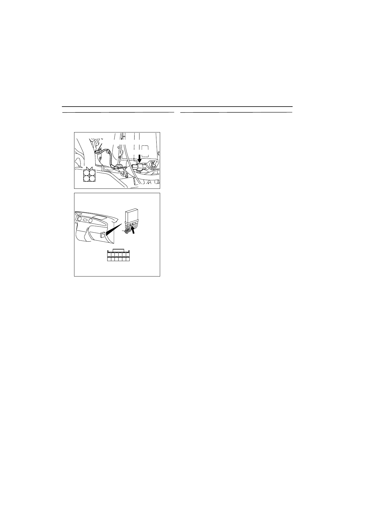
STEP 10. Check harness between B-112 (terminal 
No. 3) oxygen sensor (front) connector and C-136 
(terminal No. 60) engine-ECU connector.

œ

Check earthing line for damage.

Q: Is the check result normal?

YES : 

Go to Step 11 .

NO : 

Repair.

STEP 11. Check the trouble symptoms.

Q: Does trouble symptom persist?

YES : 

Replace engine-ECU.

NO : 

Intermittent malfunction (Refer to GROUP 
00 

-

 How to Use 

Troubleshooting/Inspection Service Points 

3

00


).

AK300264

1

2

3

4

AB

B-112 (B)

Harness side connector

Oxygen sensor (front)

Connector: B-112

AK300268

58

60

61

53 52 51

55 54

56

59

62

57

AB

CONNECTOR: C-136

C-136

Harness side connector

TROUBLESHOOTING

MULTIPORT FUEL INJECTION (MFI)

13A-72

Code No. P0136: Oxygen Sensor (Rear) System <Sensor 2>

OPERATION

œ

The sensor signal is inputted to the engine-ECU 
(terminal No. 75) from the oxygen sensor (rear) 
output terminal (terminal No. 4).

œ

The oxygen sensor (rear) (terminal No. 3) is 
earthed with engine-ECU (terminal No. 92).

FUNCTION

œ

The oxygen sensor (rear) converts the concentra-
tion of oxygen in the exhaust emission into a volt-
age signal and inputs the voltage signal to the 
engine-ECU.

œ

When the air-fuel ratio is richer than the theoreti-
cal air-fuel ratio, the oxygen sensor (rear) outputs 
a voltage of about 1 V. When it is leaner than the 
theoretical air-fuel ratio, it outputs a voltage of 
about 0 V.

œ

In response to the signal, the engine-ECU con-
trols the fuel infection amount so that the air-fuel 
ratio can be equivalent to the theoretical air-fuel 
ratio.

TROUBLE JUDGMENT

Check Conditions

œ

Above 3 minutes later after the engine has 
started up.

œ

The engine coolant temperature is approximately. 
82

•

C or higher.

œ

The engine speed is 1,200 r/min or more.

œ

The volumetric efficiency is 25% or more.

œ

The monitoring time is 5 seconds.

Judgment Criteria

œ

When the oxygen sensor (rear) output voltage is 
0.2 V or less and a power voltage of 5 V is 
applied to the oxygen sensor (rear) in the engine-
ECU, the sensor output voltage is 4.5 V or more.

PROBABLE CAUSE

œ

Failed oxygen sensor

œ

Open/short circuit in oxygen sensor (rear) circuit 
or loose connector contact

œ

Failed engine-ECU

AK300269

1 2

3 4

82

78

81

80

89 90 9192

79

87

71

74

73

72

76

75

77

85

88

83 84

86

AB

C-18

(MU801688)

Engine-ECU

Oxygen sensor (rear)

From engine control relay

To engine-ECU

2

3

P

L

B

B

1

4

92

75

Oxygen sensor (rear) circuit

3

1

J/C (2)
C-17

Wire colour code
B: Black  LG: Light green  G: Green  L: Blue  W: White  Y: Yellow  SB: Sky blue  BR: Brown  O: Orange  GR: Gray
R: Red  P: Pink  V:Violet

C-137

TROUBLESHOOTING

MULTIPORT FUEL INJECTION (MFI)

13A-73

DIAGNOSIS PROCEDURE

STEP 1. MUT-II data list

œ

Refer to Data list reference table 

3

13A


.

a. Item 59: Oxygen sensor (rear)

Q: Is the check result normal?

YES : 

Intermittent malfunction (Refer to GROUP 

00 

-

 How to Use 

Troubleshooting/Inspection Service Points 

3

00


).

NO : 

Go to Step 2 .

STEP 2. Connector check: C-18 oxygen sensor 
(rear) connector

Q: Is the check result normal?

YES : 

Go to Step 3 .

NO : 

Repair.

STEP 3. Measure voltage at C-18 oxygen sensor 
(rear) connector.

œ

Disconnect connector, and measure at harness 
side.

œ

Resistance between terminal No. 3 and earth.

OK: 2 

W

 or less

Q: Is the check result normal?

YES : 

Go to Step 7 .

NO : 

Go to Step 4 .

STEP 4. Connector check: C-137 engine-ECU 
connector

Q: Is the check result normal?

YES : 

Go to Step 5 .

NO : 

Repair.

AK300270

1 2

3 4

AB

Connector: C-18

Oxygen sensor (rear)

C-18

Harness side
connector

AK300270

1 2

3 4

AB

Connector: C-18

Oxygen sensor (rear)

C-18

Harness side
connector

AK300254

82

78

8180

89

90

91

92

79

87

71

74 73 72

76 75

77

85

88

83

84

86

AB

CONNECTOR: C-137

C-137

Harness side connector

TROUBLESHOOTING

MULTIPORT FUEL INJECTION (MFI)

13A-74

STEP 5. Check harness between C-18 (terminal 
No. 3) oxygen sensor (rear) connector and C-137 
(terminal No. 92) engine-ECU connector.

œ

Check earthing line for open circuit and damage.

Q: Is the check result normal?

YES : 

Go to Step 6 .

NO : 

Repair.

STEP 6. MUT-II data list

œ

Refer to Data list reference table 

3

13A


.

a. Item 59: Oxygen sensor (rear)

Q: Is the check result normal?

YES : 

Intermittent malfunction (Refer to GROUP 

00 

-

 How to Use 

Troubleshooting/Inspection Service Points 

3

00


).

NO : 

Replace engine-ECU.

STEP 7. Measure voltage at C-18 oxygen sensor 
(rear) connector.

œ

Use special tool test harness (MB991658) to con-
nect connector, and measure at pick-up harness.

œ

Engine: After warm-up

œ

Ignition switch: ON

œ

Voltage between terminal No. 3 and earth.

OK: 0.5 V or less

Q: Is the check result normal?

YES : 

Go to Step 9 .

NO : 

Go to Step 8 .

AK300270

1 2

3 4

AB

Connector: C-18

Oxygen sensor (rear)

C-18

Harness side
connector

AK300254

82

78

8180

89

90

91

92

79

87

71

74 73 72

76 75

77

85

88

83

84

86

AB

CONNECTOR: C-137

C-137

Harness side connector

AK300270

1 2

3 4

AB

Connector: C-18

Oxygen sensor (rear)

C-18

Harness side
connector


Content   ..  50  51  52  53   ..