Mitsubishi Outlander (2003+). Manual - part 51


  Index      Mitsubishi     Mitsubishi Outlander - service repair manual 2003 year


Search            


Content   ..  49  50  51  52   ..


Mitsubishi Outlander (2003+). Manual - part 51


TROUBLESHOOTING

MULTIPORT FUEL INJECTION (MFI)

13A-67

Code No. P0135: Oxygen Sensor Heater (Front) System <Sensor 1>
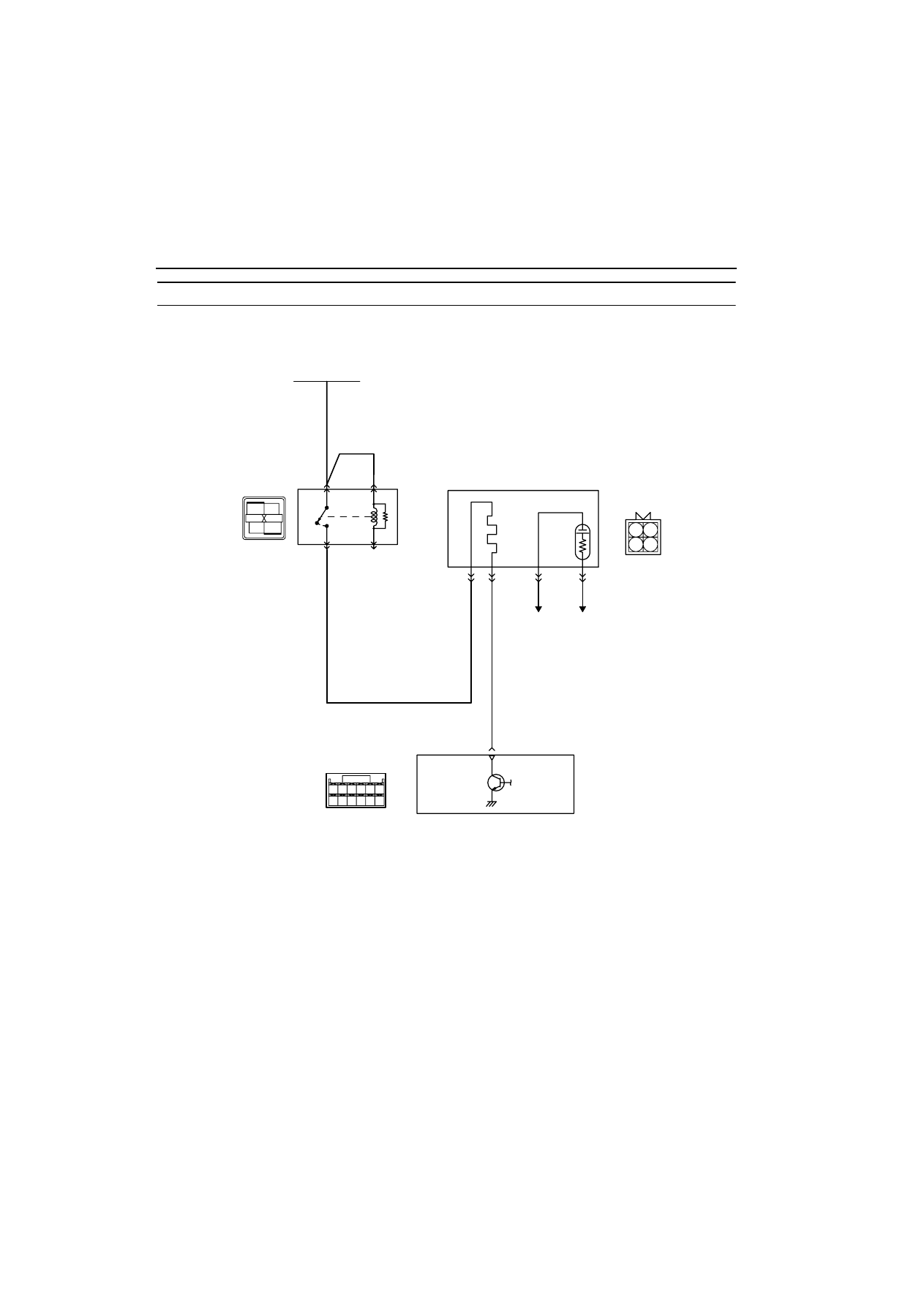
OPERATION

œ

Power is supplied to the heater power terminal 
(terminal No. 1) of the oxygen sensor (front) con-
nector from the engine control relay (terminal No. 
1).

œ

The heater (terminal No. 3) of the oxygen sensor 
(front) connector is controlled by the power tran-
sistor in the engine-ECU (terminal No. 60).

FUNCTION

œ

The power supply to the oxygen sensor heater 
(front) is controlled by the ON/OFF control of the 
power transistor in the engine-ECU.

œ

Heating the oxygen sensor heater (front) enables 
the oxygen sensor to provide good response 
even when the exhaust emission temperature is 
low.

AK300267

1

2

3

4

1

2

3

4

57 58

60 61

53

52

51

55

54

56

59

62

AB

B-17X

4

W-B

W-B

3

1

2

Oxygen sensor (front)

1

2

3

4

To engine-ECU

Engine-ECU

60

Y-R

R

Engine 
control 
relay

Oxygen sensor (front) heater circuit

     B-112
(MU8026053)

Battery

Wire colour code
B: Black  LG: Light green  G: Green  L: Blue  W: White  Y: Yellow  SB: Sky blue  BR: Brown  O: Orange  GR: Gray
R: Red  P: Pink  V:Violet

C-136

TROUBLESHOOTING

MULTIPORT FUEL INJECTION (MFI)

13A-68

TROUBLE JUDGMENT

Check Conditions

œ

The engine coolant temperature is approximately. 
20

•

C or higher.

œ

The oxygen sensor heater (front) is in "ON" posi-
tion.

œ

The engine speed is 50 r/min or more.

œ

The battery voltage is 11 

-

 16 V.

Judgment Criteria

œ

The heater current of oxygen sensor heater 
(front) is below 0.2 A or above 3.5 A for 1 second.

PROBABLE CAUSE

œ

Failed oxygen sensor heater

œ

Open/short circuit in oxygen sensor (front) circuit 
or loose connector contact

œ

Failed engine-ECU

DIAGNOSIS PROCEDURE

STEP 1. Connector check: B-112 oxygen sensor 
(front) connector

Q: Is the check result normal?

YES : 

Go to Step 2 .

NO : 

Repair.

STEP 2. Measure resistance at B-112 oxygen 
sensor (front) connector.

œ

Disconnect connector, and measure at sensor 
side.

œ

Resistance between terminal No. 1 and No. 3.

OK: 4.5 

-

 8.0 

W

Q: Is the check result normal?

YES : 

Go to Step 3 .

NO : 

Replace oxygen sensor (front).

STEP 3. Measure voltage at B-112 oxygen sensor 
(front) connector.

œ

Disconnect connector, and measure at harness 
side.

œ

Ignition switch: ON

œ

Voltage between terminal No. 1 and earth.

OK: System voltage

Q: Is the check result normal?

YES : 

Go to Step 5 .

NO : 

Go to Step 4 .

AK300264

1

2

3

4

AB

B-112 (B)

Harness side connector

Oxygen sensor (front)

Connector: B-112

AK300264

1

2

3

4

AB

B-112 (B)

Harness side connector

Oxygen sensor (front)

Connector: B-112

AK300264

1

2

3

4

AB

B-112 (B)

Harness side connector

Oxygen sensor (front)

Connector: B-112

TROUBLESHOOTING

MULTIPORT FUEL INJECTION (MFI)

13A-69

STEP 4. Connector check: B-17X engine control 
relay connector

Q: Is the check result normal?

YES : 

Check and repair harness between B-112 

(terminal No. 1) oxygen sensor connector 
and B-17X (terminal No. 1) engine control 
relay connector.

œ

Check power supply line for 
open/short circuit.

NO : 

Repair.

STEP 5. Measure voltage at C-136 engine-ECU 
connector.

œ

Measure engine-ECU terminal voltage.

œ

Ignition switch: ON

œ

Voltage between terminal No. 60 and earth.

OK: System voltage

Q: Is the check result normal?

YES : 

Go to Step 8 .

NO : 

Go to Step 6 .

STEP 6. Connector check: C-136 engine-ECU 
connector

Q: Is the check result normal?

YES : 

Go to Step 7 .

NO : 

Repair.

AK300255

2

1

3

4

Relay box’s
triangle marks

AB

CONNECTOR: B-17X

B-17X

Harness side
connector

AK300264

1

2

3

4

AB

B-112 (B)

Harness side connector

Oxygen sensor (front)

Connector: B-112

AK300268

58

60

61

53 52 51

55 54

56

59

62

57

AB

CONNECTOR: C-136

C-136

Harness side connector

AK300268

58

60

61

53 52 51

55 54

56

59

62

57

AB

CONNECTOR: C-136

C-136

Harness side connector

TROUBLESHOOTING

MULTIPORT FUEL INJECTION (MFI)

13A-70

STEP 7. Check harness between B-112 (terminal 
No. 3) oxygen sensor (front) connector and C-136 
(terminal No. 60) engine-ECU connector.

œ

Check earthing line for open/short circuit.

Q: Is the check result normal?

YES : 

Replace engine-ECU.

NO : 

Repair.

STEP 8. Connector check: C-136 engine-ECU 
connector

Q: Is the check result normal?

YES : 

Go to Step 9 .

NO : 

Repair.

STEP 9. Check harness between B-112 (terminal 
No. 1) oxygen sensor (front) connector and B-
17X (terminal No. 1) engine control relay 
connector.

œ

Check power supply line for damage.

Q: Is the check result normal?

YES : 

Go to Step 10 .

NO : 

Repair.

AK300264

1

2

3

4

AB

B-112 (B)

Harness side connector

Oxygen sensor (front)

Connector: B-112

AK300268

58

60

61

53 52 51

55 54

56

59

62

57

AB

CONNECTOR: C-136

C-136

Harness side connector

AK300268

58

60

61

53 52 51

55 54

56

59

62

57

AB

CONNECTOR: C-136

C-136

Harness side connector

AK300264

1

2

3

4

AB

B-112 (B)

Harness side connector

Oxygen sensor (front)

Connector: B-112

AK300255

2

1

3

4

Relay box’s
triangle marks

AB

CONNECTOR: B-17X

B-17X

Harness side
connector


Content   ..  49  50  51  52   ..