Mitsubishi Outlander (2003+). Manual - part 23
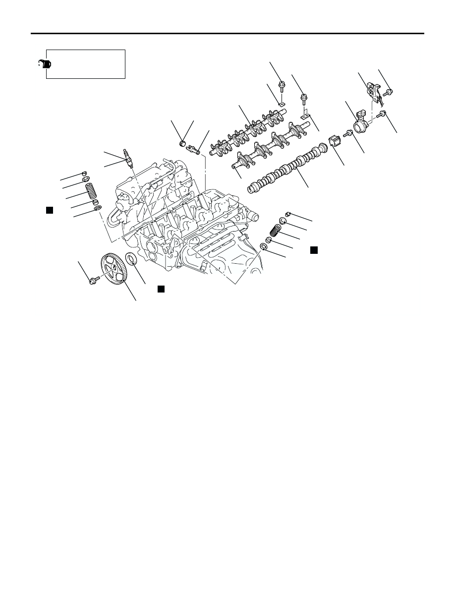
CAMSHAFT AND VALVE STEM SEAL
ENGINE MECHANICAL <4G69>
11C-19
AC308975AB
17
16
15
13
12
11
28*
27*
26*
25*
24*
22
21
20
18
19
N
28*
25*
24*
14 ± 1 N·m
22 ± 4 N·m
13 ± 1 N·m
31 ± 3 N·m
47 ± 7 N·m
25 ± 4 N·m
89 ± 9 N·m
N
N
Apply engine oil to all
moving parts before
installation.
14
23
29*
29*
11 ± 1 N·m
Camshaft removal steps
11. Connector bracket
>>I<<
12. Camshaft position sensor support
13. Camshaft position sensing cylinder
<<A>>
>>H<<
14. Camshaft sprocket
>>G<<
15. Camshaft oil seal
>>F<<
16. Exhaust rocker arm shaft caps
<<B>>
>>F<<
17. Exhaust rocker arm and shaft
assembly
>>E<<
18. Inlet rocker arm shaft caps
<<B>>
>>E<<
19. Inlet rocker arm and shaft assembly
>>D<<
20. Camshaft
•
Water inlet fitting and thermostat
case assembly (Refer to GROUP
14, Water Hose and Water Pipe
).
21. Cylinder head plug
22. Oil control valve filter
Valve stem seal removal steps
1.
Rocker cover PCV hose connection
2.
Rocker cover breather hose
connection
3.
Control wiring harness connection
4.
Engine hanger
7.
Rocker cover assembly
8.
Rocker cover gasket
9.
Spark plug guide oil seals
>>F<<
16. Exhaust rocker arm shaft caps
<<B>>
>>F<<
17. Exhaust rocker arm and shaft
assembly
>>E<<
18. Inlet rocker arm shaft caps
<<B>>
>>E<<
19. Inlet rocker arm and shaft assembly
23. Spark plugs
<<C>>
>>C<<
24. Valve spring retainer locks
25. Valve spring retainers
>>B<<
26. Inlet valve springs
>>B<<
27. Exhaust valve springs
>>A<<
28. Valve stem seals
29. Valve spring seats