Mitsubishi Montero Sport (2004+). Manual - part 816


  Index      Mitsubishi     Mitsubishi Montero Sport - service repair manual 2004 year


Search            


Content   ..  814  815  816  817   ..


Mitsubishi Montero Sport (2004+). Manual - part 816


ANTI-LOCK BRAKING SYSTEM (ABS) DIAGNOSIS

TSB Revision

ANTI-LOCK BRAKING SYSTEM (ABS) <4WD>

35C-71

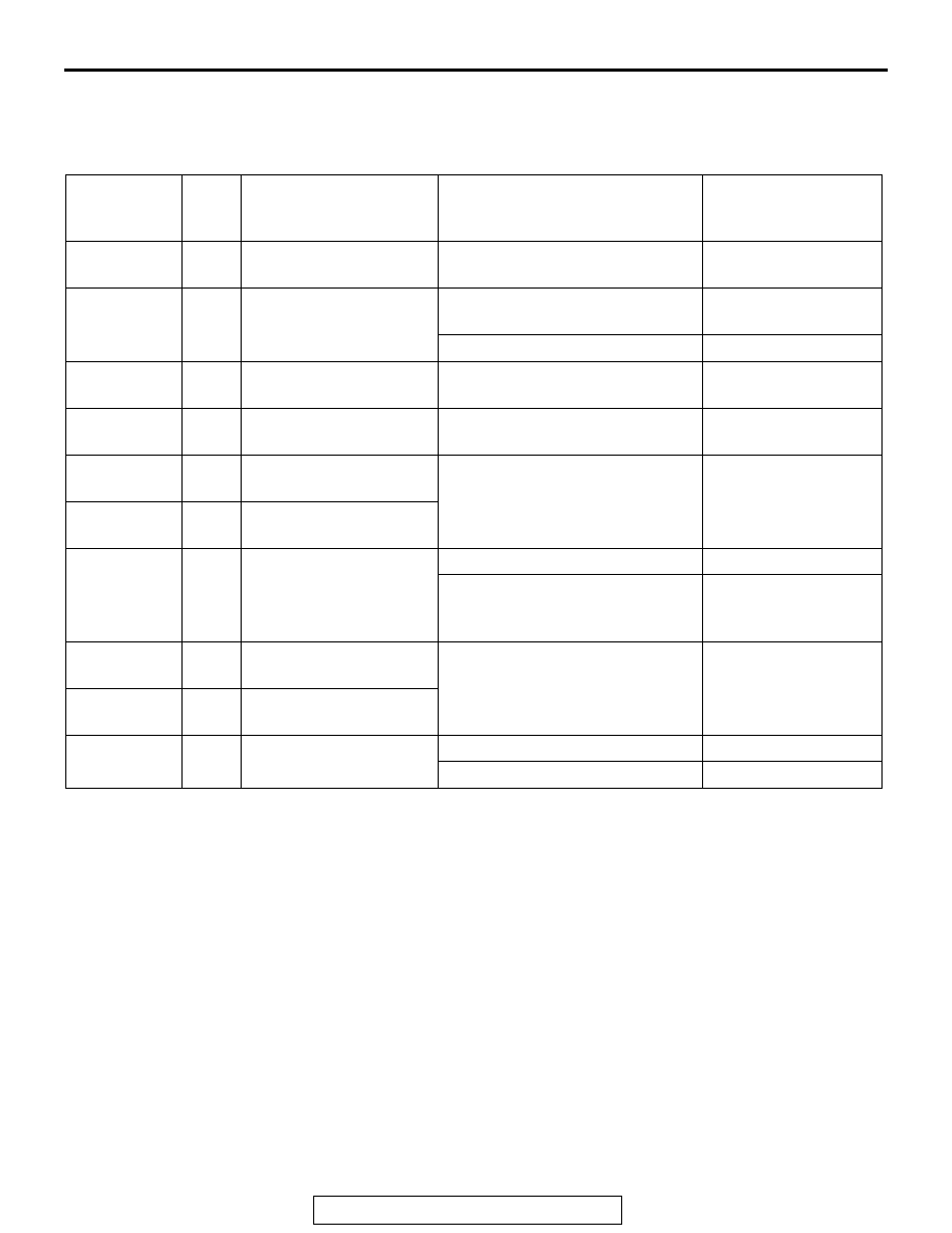
DATA LIST REFERENCE TABLE

M1352011500650

The following items can be read by the scan tool from the ABS-ECU input data.
1. When the system is normal.

2. When the ABS-ECU shuts off the ABS operation.
When the diagnostic trouble system stops the ABS-ECU, the scan tool display data will be unreliable.

MUT-III 
SCAN TOOL 
DISPLAY

ITEM 
NO.

INSPECTION ITEM

INSPECTION REQUIREMENT

NORMAL VALUE

2/4WD SW 1 25

2/4WD detection switch 
1

ON

2/4WD SW 2 26

2/4WD detection switch 
2

Transfer control lever: "4L" or 
"4H"

ON

Transfer control lever: "AWD"

OFF

R/D LOCK 
SW

27

Rear differential lock 
detection switch

OFF

BATT. 
VOLTAGE

16

ABS-ECU power supply 
voltage

Ignition switch power supply 
voltage and valve monitor voltage

6.5 

− 22.3 V

FL SNSR

12

Front left wheel speed 
sensor

Drive the vehicle.

Vehicle speeds 
displayed on the 
speedometer and 
scan tool are identical.

FR SNSR

11

Front right wheel speed 
sensor

G SNSR

32

G-sensor output voltage When vehicle is stationary (level) 2.4 

− 2.6V

When vehicle is being driven

Display value 
fluctuates with a mean 
value of 2.5V.

RL SNSR

14

Rear left wheel speed 
sensor

Drive the vehicle.

Vehicle speeds 
displayed on the 
speedometer and 
scan tool are identical.

RR SNSR

13

Rear right wheel speed 
sensor

STOPLIGHT 
SW

33

Stoplight switch

Depress the brake pedal.

ON

Release the brake pedal.

OFF

ANTI-LOCK BRAKING SYSTEM (ABS) DIAGNOSIS

TSB Revision

ANTI-LOCK BRAKING SYSTEM (ABS) <4WD>

35C-72

ACTUATOR TEST REFERENCE

M1352011600668

The scan tool activates the following actuators for testing.
NOTE: If the ABS-ECU is inoperative, actuator testing cannot be carried out.
Actuator testing is only possible when the vehicle is stationary. If the vehicle speed during actuator testing 
exceeds 10 km/h (6 mph), forced actuation will be canceled.

ACTUATOR TEST SPECIFICATIONS

MUT-III 
SCAN 
TOOL 
DISPLAY

NO.

ITEM

FR SOL 
VALVE

01

Solenoid valve 
for front-right 
wheel

Solenoid valves and 
pump motor in the 
hydraulic unit (simple 
inspection mode)

FL SOL 
VALVE

02

Solenoid valve 
for front-left 
wheel

REAR 
SOL. V.

03

Solenoid valve 
for rear wheel

AC004863 AB

A

B

C

ACTIVATION PATTERN

START OF
FORCED
ACTION

END OF
FORCED
ACTION

ON

OFF

SOLENOID
VALVE

PUMP
MOTOR

NOTE
A: HYDRAULIC PRESSURE INCREASES
B: HYDRAULIC PRESSURE HOLDS
C: HYDRAULIC PRESSURE DECREASE

48 ms

1 s

3 s

8 ms

ANTI-LOCK BRAKING SYSTEM (ABS) DIAGNOSIS

TSB Revision

ANTI-LOCK BRAKING SYSTEM (ABS) <4WD>

35C-73

CHECK AT ABS-ECU

M1352011800639

TERMINAL VOLTAGE CHECK CHART

NOTE: Do not measure terminal voltage for approximately three seconds after the ignition switch is turned 
"ON." The ABS-ECU performs the initial check during that period.

1. Measure the voltages between terminals (32) or (34) (ground terminals) and each respective terminal.
2. The terminal layouts are shown in the illustrations.

AC004864

CONNECTOR 
TERMINAL 
NO.

SIGNAL

CHECKING REQUIREMENT

NORMAL 
CONDITION

7

G-sensor

Ignition switch: "ON"

2.38 

− 2.62 V

9

ABS-ECU power 
supply

Ignition switch: "ON"

Battery positive 
voltage

Ignition switch: "START"

0 V

11

2/4WD switch 2

Ignition switch: "ON" Transfer control lever: "4L" 

or "4H"

0 V

Transfer control lever: 
"AWD"

Battery positive 
voltage

12

2/4WD switch 1

Always

0 V

13

Input from stoplight 
switch

Ignition switch: "ON" Stoplight switch: "ON"

Battery positive 
voltage

Stoplight switch: "OFF"

1 V or less

14

G sensor

Always

0 V

16

Control output to 
ABS warning light 
relay

Ignition switch: "ON" The light is switch off.

2 V or less

The light is illuminated.

Battery positive 
voltage

23

Scan tool

Connect the scan tool.

Serial 
communication 
with scan tool

Do not connect the scan tool.

1 V or less

24

Input from 
diagnostic 
indication selection

Connect the scan tool.

0 V

Do not connect the scan tool.

Approximately 
12 V

31

Solenoid valve 
power supply

Always

Battery positive 
voltage

33

Motor power 
supply

ANTI-LOCK BRAKING SYSTEM (ABS) DIAGNOSIS

TSB Revision

ANTI-LOCK BRAKING SYSTEM (ABS) <4WD>

35C-74

RESISTANCE AND CONTINUITY BETWEEN HARNESS-SIDE CONNECTOR 
TERMINALS

1. Turn the ignition switch to the "LOCK" (OFF) position and disconnect the ABS-ECU connectors before 

checking resistance and continuity.

2. Check between the terminals indicated in the table below.
3. The terminal layouts are shown in the illustration.

AC004865

CONNECTOR 
TERMINAL NO.

SIGNAL

NORMAL CONDITION

− 2

Rear-right wheel speed sensor

1.3 

− 1.5 kΩ

− 4

Rear-left wheel speed sensor

1.3 

− 1.5 kΩ

18 

− 19

Front-right wheel speed sensor

1.3 

− 1.5 kΩ

20 

− 21

Front-left wheel speed sensor

1.3 

− 1.5 kΩ

32 

− body ground

Solenoid valve ground

Continuity (Less than 2 ohms)

34 

− body ground

Motor ground

Continuity (Less than 2 ohms)


Content   ..  814  815  816  817   ..