Mitsubishi Montero Sport (2004+). Manual - part 808


  Index      Mitsubishi     Mitsubishi Montero Sport - service repair manual 2004 year


Search            


Content   ..  806  807  808  809   ..


Mitsubishi Montero Sport (2004+). Manual - part 808


ANTI-LOCK BRAKING SYSTEM (ABS) DIAGNOSIS

TSB Revision

ANTI-LOCK BRAKING SYSTEM (ABS) <4WD>

35C-39

NOTE: After inspecting G-sensor connector C-26, joint connec-
tor C-11 and junction block connector D-08 and D-13 inspect 
the wires. If G-sensor connector C-26, joint connector C-11, 
junction block connector D-08 or D-13 is damaged, repair or 
replace it. Refer to GROUP 00E, Harness Connector Inspec-
tion 

P.00E-2

. If the connector has been repaired or replaced, 

go to Step 7.
Q: Is the harness wire between G-sensor connector C-26 

(terminal No.1) and ignition switch (IG2) damaged?
YES : 
Repair it and then go to Step 7.
NO :  Go to Step 7.

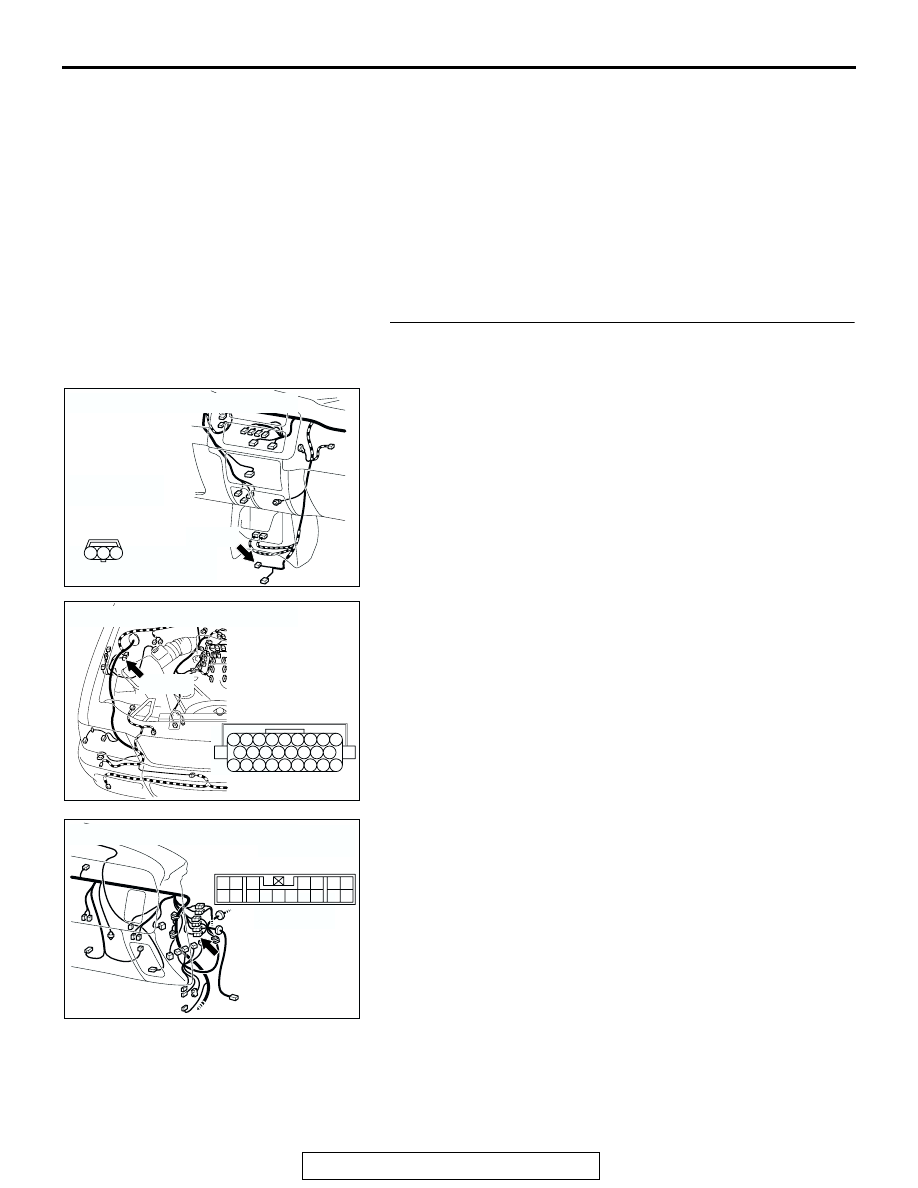
STEP 6. Check the harness wires between G-sensor 
connector C-26 (terminal No.2 and 3) and ABS-ECU 

connector A-85 (terminal No7 and 14).

AC201949

CONNECTOR : C-26

C-26(B)

C-26 HARNESS 
CONNECTOR:
COMPONENT SIDE

AB

2 1

3

AC201944

CONNECTOR : A-85 

A-85(B)

A-85 HARNESS 
CONNECTOR:
COMPONENT SIDE

AD

18

12 11

20 19

10

3 2 1

13

14

22

23

17 16

25 24

15

8 7 6 5 4

21

9

26

AC201950

CONNECTOR : C-17

C-17

AB

17

7

15

5

16

6

12 13

10

3

11

14

4

8

1

9

2

ANTI-LOCK BRAKING SYSTEM (ABS) DIAGNOSIS

TSB Revision

ANTI-LOCK BRAKING SYSTEM (ABS) <4WD>

35C-40

NOTE: After inspecting G-sensor connector C-26, intermediate 
connector C-17 and ABS-ECU connector A-85, inspect the 
wires. If G-sensor connector C-26, intermediate connector 
C-17 or ABS-ECU connector A-85 is damaged, repair or 
replace it. Refer to GROUP 00E, Harness Connector Inspec-
tion 

P.00E-2

. If the connector has been repaired or replaced, 

go to Step 7.
Q: Is the harness wire between G-sensor connector C-26 

(terminal No.2 and 3) and ABS-ECU connector A-85 
(terminal No7 and 14) damaged?
YES : 
Repair it and then go to Step 7.
NO :  Replace the hydraulic unit (integrated with ABS-ECU) 

and then go to Step 7.

STEP 7. Recheck for diagnostic trouble code.

Q: Does diagnostic trouble code 32 reset?

YES : Start over at Step 1.
NO :  The procedure is complete.

AK303629AB

MB991911

MB991827

MB991824 

16-PIN

ANTI-LOCK BRAKING SYSTEM (ABS) DIAGNOSIS

TSB Revision

ANTI-LOCK BRAKING SYSTEM (ABS) <4WD>

35C-41

DTC 33 : Stoplight Switch System

JUNCTION 
BLOCK

JUNCTION 
BLOCK

STOPLIGHT
SWITCH

ABS-ECU

FUSIBLE
LINK

8

JOINT 
CONNECTOR (2)

Stoplight Switch Circuit

ANTI-LOCK BRAKING SYSTEM (ABS) DIAGNOSIS

TSB Revision

ANTI-LOCK BRAKING SYSTEM (ABS) <4WD>

35C-42

.

CIRCUIT OPERATION
The "ON" signal when the brake pedal is pressed or 
the "OFF" signal when the brake pedal is released is 
input to the ABS-ECU (terminal 13).

.

ABS DTC SET CONDITION
DTC 33 is set in the following cases:

• Stoplight switch is not operating properly and 

remains in ON state for more than 15 minutes.

• Stoplight switch system harness is damaged and 

no signal is input to the ABS-ECU.

.

TROUBLESHOOTING HINTS (The most likely 
causes for DTC 33 to set are:)

• Malfunction of the stoplight switch

• Damaged wiring harness and connector

• Malfunction of the hydraulic unit (integrated with 

ABS-ECU) 

.

DIAGNOSIS

Required Special Tools:

• MB991223: Harness Set

• MB991958: Scan Tool (MUT-III Sub Assembly)

• MB991824: Vehicle Communication Interface (V.C.I.)

• MB991827: MUT-III USB Cable

• MB991911: MUT-III Main Harness B

AC004837

CONNECTOR: A-85

AH

A-85 (B)

AC004261

CONNECTORS: C-10, C-17

AK

C-17

C-10

AC004994 AD

C-66 (B)

CONNECTOR: C-66

AC201951

CONNECTOR : D-02

D-02(GR)

AD

AC201952

CONNECTOR : D-09

AE

D-09


Content   ..  806  807  808  809   ..