Mitsubishi Montero Sport (2004+). Manual - part 804


  Index      Mitsubishi     Mitsubishi Montero Sport - service repair manual 2004 year


Search            


Content   ..  802  803  804  805   ..


Mitsubishi Montero Sport (2004+). Manual - part 804


ANTI-LOCK BRAKING SYSTEM (ABS) DIAGNOSIS

TSB Revision

ANTI-LOCK BRAKING SYSTEM (ABS) <4WD>

35C-23

STEP 7. Check the wheel bearing.

Refer to GROUP 26, Front Hub Assembly 

P.26-16

, and 

GROUP 27, Axle Shaf

P.27-21

.

Q: Is the wheel bearing damaged?

YES :  Replace it and then go to Step 8.
NO :  Go to Step 8.

STEP 8. Recheck for diagnostic trouble code.

Q: Do diagnostic trouble code 15 reset?

YES : Go to Step 1.
NO :  The procedure is complete.
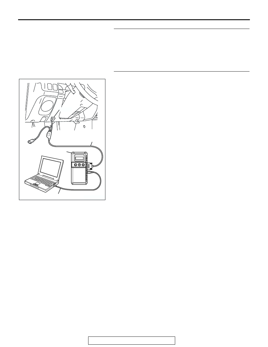
AK303629AB

MB991911

MB991827

MB991824 

16-PIN

ANTI-LOCK BRAKING SYSTEM (ABS) DIAGNOSIS

TSB Revision

ANTI-LOCK BRAKING SYSTEM (ABS) <4WD>

35C-24

DTC 16: ABS-ECU Power Supply System

JUNCTION 
BLOCK

ABS-ECU

JOINT 
CONNECTOR (1)

IGNITION
SWITCH (IG2)

Power Supply Circuit

AC004837

CONNECTOR: A-85

AH

A-85 (B)

AC004261

CONNECTORS: C-11, C-17

AJ

C-17

C-11

ANTI-LOCK BRAKING SYSTEM (ABS) DIAGNOSIS

TSB Revision

ANTI-LOCK BRAKING SYSTEM (ABS) <4WD>

35C-25

.

CIRCUIT OPERATION
The ABS-ECU power is supplied to the ABS-ECU 
(terminal 9) from the ignition switch (IG2) through the 
fuse number 4 in the junction block and through the 
joint connector number 1.

.

ABS DTC SET CONDITIONS
Output is provided when ABS-ECU power supply 
voltage drops below or rises above the normal value. 
Output is not provided if power supply voltage 
returns to normal voltage.

.

TROUBLESHOOTING HINTS
The most likely causes for DTC is to set are:

• Damaged wiring harness and connector

• Malfunction of hydraulic unit (integrated with 

ABS-ECU)

.

DIAGNOSIS

Required Special Tool:

• MB991958: Scan Tool (MUT-III Sub Assembly)

• MB991824: Vehicle Communication Interface (V.C.I.)

• MB991827: MUT-III USB Cable

• MB991911: MUT-III Main Harness B

STEP 1. Check the battery.

Refer to GROUP 54, Battery 

− On-vehicle Service − Battery 

Testing Procedure 

P.54-7

.

Q: Is the battery damaged?

YES : Charge or replace the battery and then go to Step 4.
NO :  Go to Step 2.

AC201952

CONNECTORS : D-08, D-13

D-08

D-13

AF

ANTI-LOCK BRAKING SYSTEM (ABS) DIAGNOSIS

TSB Revision

ANTI-LOCK BRAKING SYSTEM (ABS) <4WD>

35C-26

STEP 2. Measure the power supply circuit voltage at 
ABS-ECU connector A-85.

(1) Disconnect connector A-85 and measure at the harness 

side.

(2) Turn the ignition switch to the "ON" position.

(3) Measure the voltage between terminal 9 and ground.
Q: Is battery positive voltage (approximately 12 volts) 

present?
YES : 
Replace the hydraulic unit (integrated with ABS-ECU) 

and then go to Step 4.

NO :  Go to Step 3.

AC201944

CONNECTOR : A-85 

A-85(B)

A-85 HARNESS 
CONNECTOR:
COMPONENT SIDE

AD

18

12 11

20 19

10

3 2 1

13

14

22

23

17 16

25 24

15

8 7 6 5 4

21

9

26

2 1

18

10

3

4

20

21

13 12

19

11

6

7

24 23

14

15

8

9

25

26

17 16

22

5

AC202680AB

A-85 HARNESS CONNECTOR:
COMPONENT SIDE


Content   ..  802  803  804  805   ..