Mitsubishi Montero Sport (2004+). Manual - part 783


  Index      Mitsubishi     Mitsubishi Montero Sport - service repair manual 2004 year


Search            


Content   ..  781  782  783  784   ..


Mitsubishi Montero Sport (2004+). Manual - part 783


ANTI-LOCK BRAKING SYSTEM (ABS) DIAGNOSIS

TSB Revision

ANTI-LOCK BRAKING SYSTEM (ABS) <RWD>

35B-13

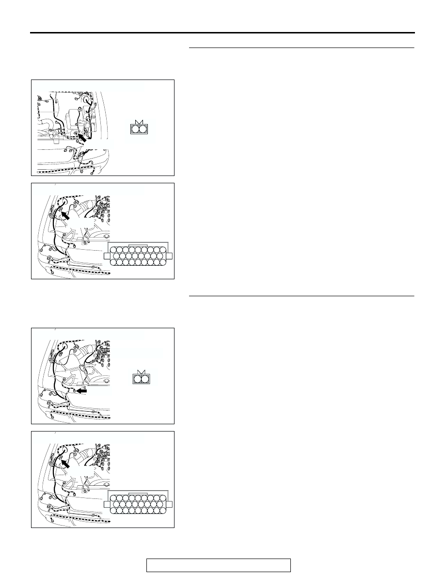
STEP 3. Check the harness wires between ABS-ECU 
connector A-85 (terminal No.20 and 21) and wheel speed 
sensor <front: LH> connector A-18 (terminal No.1 and 2).

Q: Are any harness wires between ABS-ECU connector 

A-85 (terminal No.20 and 21) and wheel speed sensor 
<front: LH> connector A-18 (terminal No.1 and 2) 
damaged?
YES : 
Repair them and go to Step 9.
NO :  Go to Step 7.

STEP 4. Check the harness wires between ABS-ECU 
connector A-85 (terminal No.18 and 19) and wheel speed 
sensor <front: RH> connector A-31 (terminal No.1 and 2).

Q: Are any harness wires between ABS-ECU connector 

A-85 (terminal No.18 and 19) and wheel speed sensor 
<front: RH> connector A-31 (terminal No.1 and 2) 
damaged?
YES : 
Repair them and then go to Step 9.
NO :  Go to Step 7.

AC201945

CONNECTOR : A-18

A-18(B)

AB

1

2

A-18 HARNESS 
CONNECTOR:
COMPONENT SIDE

2 1

AC201944

CONNECTOR : A-85 

A-85(B)

A-85 HARNESS 
CONNECTOR:
COMPONENT SIDE

AD

18

12 11

20 19

10

3 2 1

13

14

22

23

17 16

25 24

15

8 7 6 5 4

21

9

26

AC201944

CONNECTOR : A-31

A-31(B)

A-31 HARNESS 
CONNECTOR:
COMPONENT SIDE

AB

1

2

2 1

AC201944

CONNECTOR : A-85 

A-85(B)

A-85 HARNESS 
CONNECTOR:
COMPONENT SIDE

AD

18

12 11

20 19

10

3 2 1

13

14

22

23

17 16

25 24

15

8 7 6 5 4

21

9

26

ANTI-LOCK BRAKING SYSTEM (ABS) DIAGNOSIS

TSB Revision

ANTI-LOCK BRAKING SYSTEM (ABS) <RWD>

35B-14

STEP 5. Check the harness wires between ABS-ECU 
connector A-85 (terminal No.1, 2, 3 and 4) and wheel speed 
sensor connector E-29 <rear: LH> (terminal No.1 and 2) or 
E-39 <rear RH> (terminal No 1 and 2).

AC201944

CONNECTOR : A-85 

A-85(B)

A-85 HARNESS 
CONNECTOR:
COMPONENT SIDE

AD

18

12 11

20 19

10

3 2 1

13

14

22

23

17 16

25 24

15

8 7 6 5 4

21

9

26

AC201954

CONNECTOR : E-29

E-29(B)

E-29 HARNESS 
CONNECTOR:
COMPONENT SIDE

AB

1

2

AC201953

CONNECTOR : E-39

E-39(B)

E-39 HARNESS 
CONNECTOR:
COMPONENT SIDE

AB

1

2

ANTI-LOCK BRAKING SYSTEM (ABS) DIAGNOSIS

TSB Revision

ANTI-LOCK BRAKING SYSTEM (ABS) <RWD>

35B-15

NOTE: After inspecting intermediate connectors C-17 and 
E-45, inspect the wires. If intermediate connector C-17 or E-45 
is damaged, repair or replace it. Refer to GROUP 00E, Har-
ness Connector Inspection 

P.00E-2

. If the connector has been 

repaired or replaced, go to Step 9.
Q: Are any harness wires between ABS-ECU connector 

A-85 (terminal No.1, 2, 3 and 4) and wheel speed sensor 
connector E-29 <rear: LH> (terminal No.1 and 2) or E-39 
<rear RH> (terminal No.1 and 2) damaged?
YES : 
Repair them and then go to Step 9.
NO :  Go to Step 7.

STEP 6. Measure the wheel speed sensor output voltage.

Refer to 

P.35B-62

.

Output Voltage:

• When measured with a voltmeter: 70 mV or more

• When measured with oscilloscope (maximum voltage): 200 

mV or more

Q: Is the measured voltage within the specified range?

YES : Replace the hydraulic unit (integrated with ABS-ECU) 

and then go to Step 9.

NO :  Go to Step 7.

STEP 7. Check the wheel speed sensor or ABS rotor.

Refer to 

P.35B-72

. If there is damage in any of the check items 

below, replace the wheel speed sensor.

Check items:

• Wheel speed sensor internal resistance

Standard value: 1.3 

 1.5 k

• Wheel speed sensor insulation resistance

Standard value: 100 k

• Toothed ABS rotor check

Q: Is the wheel speed sensor or ABS rotor damaged?

YES :  Replace it and then go to Step 9.
NO :  Go to Step 8.

AC201950

CONNECTOR : C-17

C-17

AB

17

7

15

5

16

6

12 13

10

3

11

14

4

8

1

9

2

AC201953

CONNECTOR : E-45

E-45(B)

E-45(B)

AC

1

10

2

11

3

12

4

1314 15

5

16

6

17

7

18

8

19

9

20

ANTI-LOCK BRAKING SYSTEM (ABS) DIAGNOSIS

TSB Revision

ANTI-LOCK BRAKING SYSTEM (ABS) <RWD>

35B-16

STEP 8. Check the wheel bearing.

Refer to GROUP 26, Front Hub Assembly 

P.26-16

, and Refer 

to GROUP 27, Axle Shaft 

P.27-21

.

Q: Is the wheel bearing damaged?

YES :  Replace it and then go to Step 9.
NO :  Go to Step 9.

STEP 9. Recheck for diagnostic trouble code.

Q: Do diagnostic trouble codes 11, 12, 13, 14, 21, 22, 23 and 

24 reset?
YES : 
Go to Step 1.
NO :  The procedure is complete.

DTC 15: Wheel Speed Sensor (Abnormal Output Signal)

.

WHEEL SPEED SENSOR CIRCUIT
Refer to 

P.35B-10

.

.

CIRCUIT OPERATION
Refer to 

P.35B-10

.

.

ABS DTC SET CONDITIONS

• DTC 15 is set when output signal produced by 

any of wheel-speed sensor is abnormal (exclud-
ing short and open-circuits).

.

TROUBLESHOOTING HINTS (The most likely 
causes for these DTC to set are:)

• Improper installation of the wheel speed sensor

• Malfunction of the wheel speed sensor

• Damaged wiring harness or connector

• Malfunction of the ABS rotor

• Malfunction of the wheel bearing

• Malfunction of the hydraulic unit (integrated with 

ABS-ECU)

AK303629AB

MB991911

MB991827

MB991824 

16-PIN


Content   ..  781  782  783  784   ..