Mitsubishi Montero Sport (2004+). Manual - part 775


  Index      Mitsubishi     Mitsubishi Montero Sport - service repair manual 2004 year


Search            


Content   ..  773  774  775  776   ..


Mitsubishi Montero Sport (2004+). Manual - part 775


ON-VEHICLE SERVICE

TSB Revision

BASIC BRAKE SYSTEM

35A-25

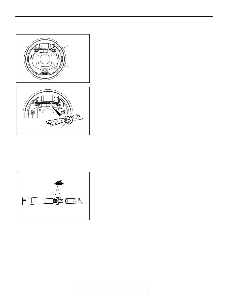
AUTO ADJUSTER FUNCTION CHECK

M1351010100300

1. Remove the brake drum.
2. Operate the parking brake lever. Observe adjuster lever 

movement for ratcheting action of the auto adjuster. Repair 
or replace the lever(s) as required.

3. Remove the shoe-to-lever spring.
4. Remove the adjuster.

NOTE: It may be necessary to rotate the adjuster wheel bot-
tom to top to release tension.

5. Inspect the adjuster wheel for wear, i.e., flat spots, worn 

teeth, etc. Replace if faulty.

6. Check both ends of the adjuster for smooth rotation. 

Replace if faulty.

7. Apply brake grease SAE J310, NLGI number 1 as shown.
8. To install adjuster, assemble the adjuster so it is at its 

minimum length and insert between shoe and lining 
assemblies.

9. Install adjuster lever and shoe-to-lever spring.
10.Rotate the adjuster wheel top to bottom until the drum has a 

slight drag when the drum is installed.

AC000894

ADJUSTER
LEVER

PARKING
BRAKE
LEVER

AB

AC000895 AB

ADJUSTER WHEEL

AC000896

ON-VEHICLE SERVICE

TSB Revision

BASIC BRAKE SYSTEM

35A-26

MASTER CYLINDER FUNCTION CHECK

M1351010200288

1. Remove the reservoir cap and diaphragm.
2. While watching the open reservoir from a distance of 50 cm 

(20 inches), have an assistant depress the brake pedal.
If there was a stream of brake fluid rising from the reservoir, 
proceed to Step 3.
If there was no stream of brake fluid rising from the 
reservoir, repair or replace the master cylinder.

3. While watching the open reservoir from a distance of 50 cm 

(20 inches), have the assistant release the brake pedal.
If there was a couple of air bubbles rising through the brake 
fluid, master cylinder function is normal.
If there were no bubbles rising through the brake fluid, repair 
or replace the master cylinder.

BRAKE PEDAL

TSB Revision

BASIC BRAKE SYSTEM

35A-27

BRAKE PEDAL

REMOVAL AND INSTALLATION

M1351003400439

Post-installation Operation
• Brake Pedal Adjustment (Refer to 

P.35A-15

.)

AC203962AB

22 N·m
16 ft-lb

29 N·m
21 ft-lb

13 N·m
115 in-lb

10

1

3

7

2

6

5

8

8

9

4

REMOVAL STEPS

1.

STOPLIGHT SWITCH

2.

BRAKE PEDAL RETURN SPRING

3.

COTTER PIN

4.

CLEVIS PIN

5.

COTTER PIN

6.

SHIFT LOCK CABLE 
CONNECTION

7.

BRAKE PEDAL

8.

BUSHING

9.

SPACER

10. PEDAL SUPPORT MEMBER

REMOVAL STEPS (Continued)

MASTER CYLINDER ASSEMBLY AND BRAKE BOOSTER

TSB Revision

BASIC BRAKE SYSTEM

35A-28

MASTER CYLINDER ASSEMBLY AND BRAKE BOOSTER

REMOVAL AND INSTALLATION

M1351003700463

CAUTION

Do not remove the check valve from the vacuum hose. If the check valve is defective, replace it 
together with the vacuum hose.

Required Special Tool:

• MB991714: Pushrod Adjust Gauge

Pre-removal Operation
• Brake Fluid Draining

• Evaporative Emission Canister Assembly Removal

(Refer to GROUP 17, Evaporative Emission Canister 

P.17-116

.)

Post-installation Operation
• Evaporative Emission Canister Assembly Installation 

(Refer to GROUP 17, Evaporative Emission Canister 

P.17-116

.)

• Brake Fluid Supplying

• Brake Line Bleeding (Refer to 

P.35A-19

.)

• Brake Pedal Adjustment (Refer to 

P.35A-15

.)

AC005039AB

13 N·m
115 in-lb

15 N·m
11 ft-lb

15 N·m
11 ft-lb

1

4

5

7

6

9

8

1

3

2

REMOVAL STEPS

1.

BRAKE TUBE CONNECTION

2.

BRAKE FLUID LEVEL SENSOR 
CONNECTOR

3.

MASTER CYLINDER ASSEMBLY

>>B<<

ADJUSTMENT OF CLEARANCE 
BETWEEN BRAKE BOOSTER 
PUSH ROD AND PRIMARY 
PISTON

>>A<<

4.

VACUUM HOSE (WITH BUILT-IN 
CHECK VALVE)

5.

COTTER PIN

6.

WASHER

7.

CLEVIS PIN

8.

BRAKE BOOSTER

9.

SEALER

REMOVAL STEPS (Continued)


Content   ..  773  774  775  776   ..